
USB-Dock-Leiterplattendesign und -fertigung für Hub-basierte Erweiterung
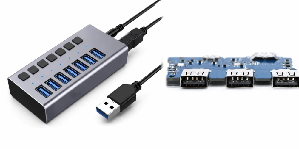
Inhaltsverzeichnis
- USB-Hub, USB-Dock und USB-C-Multifunktionsdock: Definieren Sie zuerst das Produkt.
- Upstream-USB-Architektur und Hub-Controller-Integration
- USB-C-Konfiguration, DisplayPort-Alternativmodus und Stromversorgung (sofern zutreffend)
- Hochgeschwindigkeits-Differenzialleitung und ESD-Schutz
- Downstream-Port-Stromversorgung, PD-Pfade und thermisches Design
- Leiterplattenaufbau und Fertigung für USB-Dockplatinen
- SMT-Bestückung und Port-für-Port-Funktionsprüfung
- OEM-Anfrage und Lieferantenbewertung für die Leiterplattenfertigung von USB-Docks
Eine USB-Dock-Platine sollte anhand der USB-Architektur erklärt werden. Im einfachsten Fall erweitert sie einen USB-Upstream-Anschluss auf mehrere USB-Downstream-Anschlüsse . Leistungsfähigere USB-C-Docks können über zusätzliche Controller DisplayPort Alt Mode, Stromversorgung, Ethernet, Kartenleser oder Audioübertragung bieten.
Dies unterscheidet sich davon, jede USB-Dockingstation als vollwertige Laptop-Dockingstation zu betrachten. USB-A- und USB-C-Anschlüsse bieten unterschiedliche Möglichkeiten, und selbst eine USB-C-Dockingstation unterstützt nicht automatisch Video, das Laden des Hosts oder mehrere Bildschirme.
Highleap Electronics unterstützt USB-basierte Dockingstationen mit USB-Hub-Leiterplattenfertigung , Hochgeschwindigkeitsfertigung, Montage, Beschaffung und kundenspezifischen Schnittstellentests.
1. USB-Hub, USB-Dock und USB-C-Multifunktionsdock: Definieren Sie zuerst das Produkt.
Ein USB-Hub erweitert primär die USB-Datenanschlüsse. Eine USB-Dockingstation ergänzt diese Hub-Architektur in der Regel um weitere nützliche Schnittstellen. Eine USB-C-Multifunktionsdockstation kann zusätzlich Typ-C-Funktionen wie DisplayPort Alt Mode oder Power Delivery nutzen, sofern ihre Controller und der vorgelagerte Host diese unterstützen.
Ein USB-Hub erweitert einen USB-Anschluss auf mehrere USB-Ports; eine USB-Dockingstation bietet typischerweise zusätzliche Funktionen wie Ethernet, Display-Ausgänge oder Kartenleser; eine USB-C-Multifunktionsdockstation kann auch alternative Betriebsmodi und Stromversorgung (Power Delivery) nutzen. Da sich diese Kategorien auf dem Markt überschneiden, muss der Artikel über Leiterplatten die Zielarchitektur definieren, bevor die Fertigung beschrieben wird. Andernfalls besteht die Gefahr, dass Produkte, die lediglich USB-Daten übertragen, auch Display- oder Ladefunktionen erhalten.
Produkttypgrenze
| Typ | Kernfunktion | Optionale Ergänzungen |
|---|---|---|
| USB-Hub | USB-Upstream zu mehreren USB-Downstream-Ports | Leistungsmanagement pro Port. |
| USB-Dock | USB-Erweiterung plus Nicht-USB-Funktionen | Ethernet, Audio, Kartenleser, Displaykonvertierung. |
| USB-C Multifunktions-Dock | Typ-C-Upstream mit USB-Erweiterung | DP-Alternativmodus, PD, zusätzliche Typ-C-Anschlüsse, je nach Ausführung. |
| Thunderbolt/USB4-Dockingstation | Protokoll-Tunneling-Hochgeschwindigkeits-Fabric | Wird separat behandelt; nicht vergleichbar mit einer herkömmlichen USB-Dockingstation. |
Für die Fertigung dient diese Definition als Port-Map und Blockdiagramm. Sie identifiziert die Upstream-Schnittstelle, Hub-Ebenen, Downstream-Ports, optionale Bridges und Stromversorgungsfunktionen. Diese Informationen sind Grundlage für die Controller-Programmierung, die Stücklistenerstellung und die Funktionstests. Eine gut strukturierte Angebotsanfrage sollte diese Definition daher zusammen mit den Gerber- und Stücklistendateien enthalten, anstatt zu erwarten, dass der Assembler die Funktionalität anhand der Steckverbinder-Footprints rekonstruiert.
Ein USB-Hub erweitert primär die USB-Anschlüsse; eine USB-Dockingstation bietet üblicherweise zusätzliche Funktionen wie Display- oder Ethernet-Anschluss; eine USB-C-Multifunktionsdockstation kann auch die Stromversorgung aushandeln oder alternative Betriebsmodi nutzen. Da diese Bezeichnungen im Marketing oft verwechselt werden, sollte die Fertigung mit einer Funktionsbeschreibung anstelle eines Produktnamens beginnen. Die Upstream-Schnittstelle, die Downstream-Anschlüsse und die Stromversorgung bestimmen die Controller, das Routing und den Testplan.
Das praktischste Dokument ist ein Blockdiagramm mit Portmatrix. Es zeigt an, welche Schnittstellen über einen Hub-Controller laufen, welche Funktionen separate Bridge-Geräte nutzen und welche USB-C-Ports – sofern implementiert – als Quelle, Senke oder Dual-Role fungieren. Dadurch wird auch vermieden, dass interne Verlinkungs-/SEO-Fachbegriffe zu technischen Behauptungen werden: Der Artikel kann optionale DP-Alt-Mode- oder PD-Funktionen erwähnen, ohne zu implizieren, dass jede USB-Dockingstation diese unterstützt.
2. Upstream-USB-Architektur und Hub-Controller-Integration
Die Upstream-Schnittstelle und der Hub-Controller definieren den verfügbaren USB-Datenpfad. USB 2.0- und USB 3.x-Signalisierungen haben unterschiedliche Routing- und Testanforderungen, und das Produkt kann aus Gründen der Abwärtskompatibilität mehrere Generationen unterstützen.
Der Upstream-USB-Pfad legt die Datenkapazität fest, die vom restlichen Hub genutzt werden kann. Hub-Controller-Auswahl, Quarz/Taktung, EEPROM- oder Firmware-Konfiguration, Reset-Sequenz und Downstream-Port-Zuordnung müssen dem veröffentlichten Design entsprechen. USB 2.0- und SuperSpeed-Pfade können zwar parallel existieren, haben aber sehr unterschiedliche Routing-Anforderungen und sollten daher nicht als ein einziges „USB-Signal“ betrachtet werden.
Die MPN des Controllers, die Referenztaktung, die EEPROM-/Firmware-Konfiguration und die Zuordnung der Downstream-Ports sollten revisionssicher sein. Der Kauf eines alternativen Hub-Controllers ist nicht ohne Weiteres möglich, wenn sich dadurch die Firmware, die Lane-Zuordnung, das Energieverhalten oder die Treiberkompatibilität ändern.
Bei der Fertigung müssen die Widerstände des Hub-Controllers, der Konfigurationsspeicher und die zugelassenen Taktgeberbauteile erhalten bleiben, da bereits kleine Änderungen in der Stückliste die Enumeration oder das Portverhalten beeinflussen können. Überprüfen Sie während der Erstmusterfertigung die Geräteidentität und die Portzuordnung vor der Serienproduktion. Dadurch werden Konfigurationsfehler früher erkannt als bei der Endprüfung, bei der die Platine zwar die Enumeration durchführen kann, aber die falsche Anzahl oder den falschen Porttyp anzeigt.
Die Hub-Topologie beeinflusst auch die Bandbreitenverteilung und das Portverhalten. Kaskadierte Hub-Stufen, interne Bridge-Geräte und Transaktionsübersetzer können Abhängigkeiten erzeugen, die allein anhand der Anzahl der Anschlüsse nicht erkennbar sind. Die Fabrik muss diese Topologie nicht neu gestalten, sollte aber vor dem Endtest sicherstellen, dass die korrekte Controller-Konfiguration für die freigegebene Portzuordnung geladen ist.
Der Upstream-USB-Pfad legt die Bandbreite und Topologie fest, die dem restlichen Dock zur Verfügung stehen. Ein Hub-Controller verteilt den USB-Datenverkehr an die Downstream-Ports und kann intern über USB Verbindungen zu Ethernet-, Audio- oder Kartenleserfunktionen herstellen. Controller-Taktung, Referenzspannungen, EEPROM/Konfiguration und High-Speed-Breakout sind daher zentrale Fertigungsmerkmale. Ein fehlerhaftes Konfigurationsimage oder ein defektes Oszillatorbauteil können selbst bei einwandfreier Lötung zu Fehlern führen.
Das Routing sollte die Geometrie der Differenzialpaare, die Referenzebenen und die im Design definierten Steckeranschlüsse beibehalten. Der Testplan sollte die vorgesehene USB-Generation mithilfe geeigneter Hosts und Geräte verifizieren, anstatt lediglich die Erkennung durch eine langsame Maus zu prüfen. Verfügt das Produkt über mehrere Downstream-Funktionen mit hoher Bandbreite, können NPI-Tests unter gleichzeitigem Datenverkehr Leistungs- oder Wärmeinteraktionen aufdecken, die bei einem Einzelporttest unentdeckt bleiben.
Architektur-Checkpoint
Geben Sie in der Angebotsanfrage die USB-Generation des Upstream-USB-Anschlusses an und listen Sie auf, welche Downstream-Funktionen den Hub gemeinsam nutzen. Dies ermöglicht Highleap die Überprüfung der Controller-Konfiguration, des bandbreitenabhängigen Routings und einer realistischen Testumgebung.
3. USB-C-Konfiguration, DisplayPort-Alternativmodus und Stromversorgung (sofern zutreffend)
Bei USB-C-Produkten kann die Leiterplatte Steuerung für Typ-C/CC oder PD , Orientierungsmultiplexing und Hochgeschwindigkeits-Leitungsführung umfassen. Der DisplayPort-Alternativmodus nutzt, sofern unterstützt, die Hochgeschwindigkeitsleitungen von Typ-C für DisplayPort; USB PD verhandelt die Stromversorgung unabhängig.
Eine USB-C-Buchse kann entweder nur grundlegende USB-Daten übertragen oder eine deutlich umfangreichere Kombination von Funktionen bieten. DisplayPort Alt Mode, USB Power Delivery und schnellere USB/USB4-Funktionen hängen von den Fähigkeiten des Controllers und dem Systemdesign ab. Der Artikel sollte daher bedingte Formulierungen verwenden und die Portrollendefinition des jeweiligen Projekts fordern, anstatt diese Funktionen als USB-C-eigene Eigenschaften darzustellen.
Da diese Funktionen optional sind, sollte die Fertigungsverpackung angeben, ob der Upstream-Port nur Daten überträgt, den Alternativmodus unterstützt, PD-Stromversorgung aufnimmt oder bereitstellt und welche Downstream-Typ-C-Ports welche Funktionen haben. Portbezeichnungen allein reichen für eine Produktionsdefinition nicht aus.
USB-C sollte nicht überbewertet werden.
Ein USB-C-Anschluss kann an einer Dockingstation vorhanden sein, die weder das Laden des Hosts noch Videoübertragung unterstützt. Veröffentlichen und testen Sie nur die Funktionen, die von der Produktarchitektur implementiert werden.
Bei Verwendung des Alternativmodus oder PD-Modus kann die Leiterplatte CC/PD-Steuerung, Lane-Multiplexing, Signalaufbereitung und geschützte Hochstrompfade hinzufügen. Firmware und zugelassene Signalpfadkomponenten werden Teil der validierten Konfiguration. Die Werksprüfung sollte die vom Kunden spezifizierten ausgehandelten Modi bestätigen, während die Konformitäts-/Zertifizierungsprüfung von den routinemäßigen Funktionsprüfungen der Leiterplatte getrennt bleibt.
USB Typ-C stellt über den reversiblen Anschluss hinaus zusätzliche Anforderungen an Konfiguration und Energiemanagement. Die CC-Pins bestimmen das Verhalten beim Einstecken bzw. in der Ausrichtung, während USB Power Delivery und alternative Modi die entsprechenden Controller und Protokollunterstützung erfordern. Eine USB-C-Buchse an einer Dockingstation kann daher je nach Design nur Daten übertragen, laden, ein Display anschließen oder multifunktional sein.
Die Fertigung sollte die Erdung des Typ-C-Steckergehäuses, den High-Speed-Lane-Breakout, die CC/PD-Komponentenbestückung, den VBUS-Schutz und alle Lane-Multiplexer/Brückengeräte kontrollieren. Die Produktionsprüfung sollte explizite Funktionserwartungen für jeden Port festlegen. Wenn ein Typ-C-Downstream-Port kein Video unterstützt, ist dies kein Fehler; wenn ein anderer Port die Stromversorgung aushandeln soll, sollte das PD-Verhalten mit definierter Ausrüstung überprüft werden. Dies vermeidet übermäßige Tests oder die Angabe nicht unterstützter Funktionen.
Highleap Electronics • Leiterplattenfertigung & PCBA
USB-Dock-PCBA-Fertigungsbericht
Teilen Sie die Anforderungen an Hub, Stromversorgung, Anschlüsse und Porttests für den Aufbau einer kontrollierten Dockingstation mit.
Angebot für USB-Dock anfordern → USB-Dock-PCBA besprechen →
✓ DFM- und DFA-Prüfung ✓ Prototypenentwicklung bis Serienproduktion ✓ Leiterplattenfertigung und -bestückung
4. Hochgeschwindigkeits-Differenzialleitung und ESD-Schutz
USB-SuperSpeed-Leitungen reagieren empfindlich auf Impedanz, Diskontinuitäten und die Qualität des Rückleitungspfads . Steckverbinderanschlüsse, ESD-Bauteile, Gleichtaktkomponenten (sofern verwendet), Durchkontaktierungen und Schichtübergänge tragen alle zum Kanal bei.
Die SuperSpeed-USB-Leitung reagiert empfindlich auf Impedanzsprünge, Stichleitungen und parasitäre Kapazitäten von Schutzkomponenten. Steckeranschluss, ESD-Schutzeinrichtung, Gleichtaktdrossel (sofern verwendet), Via-Feld und Controller-Ausgänge tragen alle zur Impedanz des Kanals bei. Der Hersteller sollte sich an den freigegebenen Stack-Up- und Controlled-Net-Anforderungen orientieren und die Impedanz nicht nur als finale, rein auf einem Testmuster basierende Messung betrachten.
Die Leiterplattenfertigung kann Leiterplatten mit kontrollierter Impedanz herstellen und die Anforderungen an Hochgeschwindigkeits-Leiterplatten mit dem Kunden-Stack-up abgleichen. Der ESD-Schutz muss gemäß dem freigegebenen Design platziert und bestückt werden; das Hinzufügen übermäßiger Kapazität durch nicht zugelassene Komponenten kann die Hochgeschwindigkeitsmargen beeinträchtigen.
- Differentialpaargeometrie und Referenzebenen beibehalten.
- Minimieren Sie ungeplante Stubs und unnötige Layerübergänge.
- Achten Sie darauf, dass Schutz- und Anschlussflächen mit qualifizierten Bauteilen verknüpft sind.
- Definieren Sie die Impedanz und alle Anforderungen an Gutachten/Tests in den Fertigungsunterlagen.
Auch der ESD-Schutz birgt Beschaffungsrisiken. Der Austausch eines Schutzbauelements gegen ein solches mit deutlich abweichender Kapazität oder Gehäusegeometrie kann die Hochgeschwindigkeitsreserve verringern, selbst wenn dessen Stoßspannungsfestigkeit ausreichend erscheint. Daher ist für Signalwegänderungen eine technische Genehmigung erforderlich. Genau diese Details machen den Artikel für den Einkauf professionell nützlich, anstatt „ESD-Schutz“ lediglich als Merkmal aufzulisten.
USB-Funktionalität vor Preisgestaltung festlegen
Geben Sie vor der Angebotserstellung die USB-Generation des Upstream-Anschlusses, die Downstream-Porttypen, das Bus-/selbstversorgte Modell sowie alle Alt-Mode- oder PD-Funktionen an. Dieses Architekturblatt verhindert sowohl Überdimensionierung als auch unzureichende Testabdeckung.
Bei SuperSpeed-Leiterbahnen umfasst der elektrische Pfad das Controller-Gehäuse, Leiterbahnen, Durchkontaktierungen, ESD-Bauteile, Steckverbinder und Kabel. Ein sauberes Layout kann an Sicherheit verlieren, wenn eine alternative Schutzbauelement-Lösung eine höhere parasitäre Kapazität aufweist oder sich der Schichtaufbau bei der Fertigung ändert. Zugelassene Bauteile und kontrollierte Impedanz sollten daher gemeinsam und nicht als separate Beschaffungs- und Leiterplattenthemen behandelt werden.
Der ESD-Schutz benötigt einen kurzen Pfad zur vorgesehenen Referenz-/Gehäusemasse, ohne dabei das Hochgeschwindigkeitssignal übermäßig zu belasten. Die genaue Positionierung ist eine Designentscheidung, sollte aber bei der Montage beibehalten werden, um Nacharbeiten durch zusätzliche lange Jumper zu vermeiden. Falls der Kunde elektrische Konformitätsmessungen verlangt, sind diese separat von den üblichen Funktionstests in der Produktion zu definieren. Ein erfolgreicher Datentransfer ist zwar ein nützliches Screening, ersetzt aber keine formale USB-Konformitätszertifizierung.
5. Stromversorgung des nachgeschalteten Ports, PD-Pfade und thermisches Design
Selbst ein reiner Daten-USB-Hub versorgt nachgeschaltete Geräte mit Strom. Leistungsfähigere Dockingstationen bieten zusätzliche USB-C-Anschlüsse mit höherer Leistung oder die Möglichkeit, das Gerät selbst zu laden. Dadurch rücken Strombelastbarkeit der Anschlüsse, Leistungsschalter , Schutzmechanismen und die Wärmeableitung des Reglers in den Fokus der Leiterplattenentwicklung.
Die Stromversorgung der Downstream-Ports muss für die gesamte Dockingstation budgetiert werden. Bei busgespeisten Systemen ist die Leistung durch die verfügbare Upstream-Verbindung begrenzt; selbstversorgende Dockingstationen verfügen zwar über mehr verfügbare Leistung, benötigen aber dennoch Strombegrenzung, Schutzfunktionen und ein Wärmemanagement für jede Portgruppe. Typ-C-Downstream-Ports können je nach Ausführung auch ein eigenes Stromverhalten oder ein eigenes Teilentladungsverhalten aufweisen.
Der Leistungsbedarf sollte als Budget pro Port und auf Systemebene angegeben werden. Leiterplattenhersteller und Bestücker können Kupferleiterbahnen und thermische Eigenschaften optimieren, während Funktionstests die Strombegrenzung bzw. das Teilentladungsverhalten gemäß den Kundenvorgaben überprüfen.
Die thermische Bewertung sollte sich auf das freigegebene Leistungsbudget und das Lastszenario beziehen und nicht auf eine allgemeine Aussage zur Nennleistung von USB-Docks.
Bei der Leiterplattenfertigung sollten Hochstromflächen, Kupferleitungen für Steckverbinder und thermische Eigenschaften erhalten bleiben, während Funktionstests die vom Kunden definierten Lastfälle simulieren. Ein Port, der Daten durchlässt, beweist nicht die korrekte Stromversorgung, und eine Leerlaufspannungsprüfung belegt nicht die Stromverteilung bei mehreren Geräten. Die Definition repräsentativer Lastkombinationen für die Produktinitiierung (NPI) liefert der Entwicklung deutlich aussagekräftigere Nachweise vor der Serienfreigabe.
Die Stromversorgung der Downstream-Ports kann selbst ohne das Laden eines Laptops mit hoher Wattzahl ein wesentlicher Bestandteil einer USB-Dockingstation sein. Da mehrere Ports gleichzeitig Strom ziehen können, müssen Lastschalter, Strombegrenzungsbauteile, Steckverbinder und die Kupferverteilung bereits in der Konstruktionsphase dimensioniert und in der Fertigung entsprechend angepasst werden. Ein Test, der lediglich die Leerlaufspannung VBUS prüft, kann Spannungsabfälle oder thermische Probleme unter realer Peripherielast übersehen.
Bei Verwendung von PD (Partitionsdetektion) müssen die ausgehandelten Spannungs-/Strommodi und die Leistungsrichtung klar dokumentiert werden. Die Leiterplatte kann mehrere Leistungsbereiche mit unterschiedlichen Schutz- und Erfassungsanforderungen aufweisen. Messen Sie während der Produktinitiierung repräsentative, belastete Anschlüsse und identifizieren Sie die Komponenten, die den größten Temperaturanstieg verursachen. Diese Informationen können die Stichprobenprüfung in der Produktion unterstützen, ohne dass jedes Gerät einem langen thermischen Belastungstest unterzogen werden muss.
Strom-/Testumwandlungspunkt
Wenn Ihre USB-Dockingstation mehrere nachgeschaltete Geräte mit Strom versorgt oder PD (Power Delivery) aushandelt, geben Sie die Strom-/Leistungsannahmen pro Port in der Angebotsanfrage an. Highleap kann die Kupferleitungen überprüfen und einen Lasttest erstellen, der der gewünschten Produktvariante entspricht.
6. Leiterplattenaufbau und Fertigung für USB-Dockplatinen
Die korrekte Lagenanzahl hängt von der Anzahl der SuperSpeed-Lanes, optionalen Display-/Netzwerkschnittstellen, der Stromverteilung und der Platinenfläche ab. Ein kleiner USB-Hub kann deutlich einfacher sein als eine multifunktionale USB-C-Dockingstation, obwohl beide auf das Stichwort „USB-Dock“ abzielen.
Die Anzahl der Lagen einer USB-Dockingstation hängt von der Portgeschwindigkeit, der Controllerdichte und optionalen Display-/Netzwerkfunktionen ab. Ein einfacher Hub kann relativ kompakt sein; eine Multifunktions-Dockingstation benötigt unter Umständen mehr Referenzebenen und Routing-Lagen. Der Lagenaufbau sollte SuperSpeed-Paare nahe an durchgehenden Referenzen platzieren, ausreichend Kupfer für die Stromwandlung bereitstellen und die Bildung von Ebenenaufteilungen unterhalb empfindlicher Leiterbahnen vermeiden.
Mehrlagige Leiterplatten, Durchkontaktierungen und komplexe Materialien werden nur dann eingesetzt, wenn die Anforderungen an Signalintegrität und Packungsdichte erfüllt werden müssen. Die Fertigungskapazität ermöglicht die Herstellung mehrlagiger Leiterplatten, sofern dies vom Design gefordert wird.
Bei der Fertigungsprüfung sollten auch die Kantendichte und die mechanische Planheit der Steckverbinder berücksichtigt werden. Große USB-A-, Typ-C-, HDMI- oder Ethernet-Steckverbinder können Spannungen entlang der Platinenkante verursachen, und ungleichmäßige Kupferschichten oder dünne Konstruktionen können die Koplanarität beeinträchtigen. Panelisierung, Werkzeugbau und Depanelisierungsstrategie sollten vor der Markteinführung festgelegt werden, damit Ausrichtungsprobleme der Steckverbinder nicht erst bei der Gehäusemontage entdeckt werden.
Die Fertigungshinweise sollten angeben, welche Differenzialpaare eine kontrollierte Impedanz erfordern, welche Durchkontaktierungen oder Stichleitungen eingeschränkt sind und ob Materialverlustgrenzen spezifiziert sind. Dadurch wird verhindert, dass eine kostengünstige Hub-Platine wie bei einem Thunderbolt-Design überdimensioniert ist, während gleichzeitig eine multifunktionale USB-Dockingstation die notwendigen Steuerungsmöglichkeiten für ihre SuperSpeed- und Display-Pfade erhält.
Die Konstruktion von USB-Dockplatinen sollte auf Hochgeschwindigkeits-Leiterbahnführung und hohe Anschlussdichte ausgelegt sein. Ein herkömmlicher Mehrlagenaufbau kann ausreichend sein; ein dicht bestückter Controller oder ein kompaktes Gehäuse können Blind-Vias oder HDI rechtfertigen. Die Fertigungszeichnung sollte alle Impedanzkontrollnetze, Anforderungen an die Enddicke sowie mechanisch kritische Schlitze oder Kanten um die Anschlüsse herum spezifizieren.
Die Kupferverteilung ist wichtig, da Dockplatinen große Leistungsbereiche neben dünn besiedelten Hochgeschwindigkeitsbereichen aufweisen können. Eine ungleichmäßige Kupferverteilung kann zu Verformungen oder Abweichungen in der Beschichtung führen, was wiederum die Ausrichtung der Steckverbinder und die Feinrasterung beeinträchtigt. Das Paneldesign sollte hervorstehende Steckverbinder schützen und eine ausreichende Unterstützung durch die SMD-Bestückung gewährleisten. Diese Fertigungsdetails haben oft einen größeren Einfluss auf die Ausbeute als eine einfache Erhöhung der Lagenanzahl.
7. SMT-Bestückung und Port-für-Port-Funktionsprüfung
Die Baugruppe kombiniert Hubs/Controller, Leistungshalbleiter, ESD-Komponenten und mechanisch belastete Steckverbinder. Vor der Weiterverarbeitung der Charge sollten die Erststückprüfungen Steckverbindertyp, Ausrichtung, Optionsbelegung und programmierte Konfiguration bestätigen.
Die Prozesskontrolle der Montage sollte die Mischung aus Feinraster-Hub-/Brücken-Controllern, kleinen ESD-Bauteilen, Leistungshalbleitern und großen Steckverbindern berücksichtigen. Die Erststückprüfung ist besonders bei Mehrfachplatinen sinnvoll, da ähnliche Steckverbinder oder wiederholte ESD-Arrays an mehreren Positionen fehlerhaft bestückt werden können. Sekundäre Löt- oder manuelle Eingriffe sollten im Fertigungsbegleitpapier explizit vermerkt und nicht der Interpretation des Bedieners überlassen werden.
Ein Testplan für eine USB-Dockingstation sollte alle vorhandenen Anschlüsse auflisten. Die USB-2.0/3.x-Kommunikation wird gegebenenfalls getestet, anschließend werden optionale Ethernet-, Display-, Kartenleser-, Audio- oder PD-Funktionen separat geprüft. Die Produktion kann Funktionstests anhand kundenspezifischer Verfahren und Vorrichtungen durchführen.
Testunterscheidung
Ein Port, der 5 V liefert, überträgt nicht zwangsläufig USB-Daten, und ein USB-C-Port, der Daten auflistet, überträgt nicht zwangsläufig Video oder ein angefordertes PD-Profil. Testen Sie jede Funktion explizit.
Der End-of-Line-Test sollte die freigegebene Portbelegung durchlaufen: Upstream-Enumeration, jeder Downstream-USB-Port, optionale Ethernet-/Display-/Kartenschnittstellen und Stromversorgungsfunktionen. Unterstützt die Leiterplatte mehrere SKUs, sollte die Testsoftware die korrekte Variante erkennen oder ihr zugewiesen werden, damit absichtlich nicht belegte Ports keine Fehlalarme auslösen. Nachvollziehbare Ergebnisse helfen zudem dabei, festzustellen, ob ein Feldproblem schnittstellenspezifisch oder chargenweit auftritt.
Die Baugruppe umfasst einen Hub-/Controller-IC, Leistungsschalter/Regler, ESD-Schutzelemente, Oszillatoren, passive Bauelemente und verschiedene Steckverbindertypen. Bei der Erstmusterprüfung sollten die Controller-Konfigurationskomponenten und die Teilenummern der Steckverbinder überprüft werden, da ähnliche Gehäuse unterschiedliche elektrische Funktionen erfüllen können. Die Lötqualität wird mittels AOI und Röntgenprüfung geprüft, während die korrekte Steckverbindung durch mechanische Steckprüfungen bestätigt wird.
Die Port-für-Port-Prüfung sollte die Upstream-Verbindung und alle angeschlossenen Downstream-Funktionen umfassen. Eine robuste Testvorrichtung kann Loopback-Geräte oder bekannte Peripheriegeräte für USB-Daten verwenden und, falls vorhanden, separate Prüfungen für Ethernet-/Display-Funktionen durchführen. Fehler sollten nach Port und Modus protokolliert werden, damit die Ursache auf die Steckerbaugruppe, die Stromversorgung, die Konfiguration oder das Verhalten des Hochgeschwindigkeitskanals zurückgeführt werden kann und nicht nur ein allgemeiner „Dock-Fehler“ vorliegt.
8. OEM-Anfrage und Lieferantenbewertung für die Leiterplattenfertigung von USB-Docks
Eine Angebotsanfrage für eine USB-Dock-Leiterplatte sollte Angaben zu Upstream-Anschluss/-typ, USB-Generationen, Downstream-Portbelegung, Typ-C-Funktionen, Anforderungen an den Alternativmodus/PD, optionalen Controllern, Stack-Up und Testmatrix enthalten. Dadurch wird verhindert, dass ein allgemeines Angebot die tatsächliche Komplexität des Docks verschleiert.
Fazit
Die Entwicklung von USB-Docks beginnt mit der USB-Hub-/Datenarchitektur. Zusätzliche Anzeige-, Netzwerk- und Ladefunktionen sollten nur dann hinzugefügt werden, wenn die Controller diese unterstützen. Dadurch unterscheidet sich diese Seite sowohl von allgemeinen Dockingstationen als auch von Thunderbolt-Docks.
Für die Beschaffung von Schnittstellencontrollern, USB-C/PD-Geräten, Schutzbauteilen und Steckverbindern sollten kontrollierte Alternativen verfügbar sein, da Änderungen die Firmware, den Hochgeschwindigkeitsverlust oder die mechanische Passung beeinträchtigen können. Passive Alternativen können erst nach Überprüfung der relevanten elektrischen Parameter breiter gestreut werden. Langfristige Projekte profitieren davon, die Controller-Firmware/-Konfiguration und den EEPROM-Inhalt an die Hardware-Revision anzupassen.
Eine vollständige Angebotsanfrage (RFQ) sollte den Upstream-USB-Modus, die Downstream-Portmatrix, die Stromversorgungsfunktionen, die Impedanzdaten, die Stückliste/Produktliste, die Firmware/Konfiguration und die Anforderungen an Funktionstests enthalten. Highleap kann so Angebote für Fertigung, Montage und Schnittstellentests erstellen, ohne nicht vorhandene Display-, Ethernet- oder PD-Funktionen vorauszusetzen. Für eine USB-Dock-Leiterplatte ist diese protokoll- und portbasierte Definition der Schlüssel zu technischer Genauigkeit und Transparenz.
RFQ-Umwandlungspunkt
Senden Sie bitte das Blockdiagramm und die Port-Feature-Matrix zusammen mit den Fertigungsdateien. Highleap kann anhand dieser Daten die Abhängigkeiten hinsichtlich Hochgeschwindigkeit, Stromversorgung und Tests ermitteln und Ihnen ein präziseres Angebot für eine USB-Dock-PCBA unterbreiten.

Empfohlen Beiträge

TMM4 Filter-Leiterplattenfertigung
Die Herstellung der Leiterplatten für den TMM4-Filter wird gesteuert durch...

TMM3 Leiterplattenfertigung für HF-Module
Die Fertigung von TMM3-Leiterplatten ist am sinnvollsten dort, wo das HF-Modul...

TMM6 Leiterplattenfertigung
TMM6-Fertigung ist die Prozesssteuerungsseite für eine mittlere Dk...

TMM10 Leiterplattenfertigung für kompakte HF-Designs
Inhaltsverzeichnis: Wie TMM10 HF-Strukturen verkleinert – TMM10 vs. ...
So erhalten Sie ein Angebot für Leiterplatten
Wir führen gerne eine DFM/DFA-Analyse für Sie durch und senden Ihnen anschließend einen Bericht zu. Sie können Ihre Dateien sicher über unsere Website hochladen. Für die Erstellung eines Angebots benötigen wir folgende Informationen:
-
- Gerber, ODB++ oder .pcb, Spezifikation.
- Stückliste, wenn Sie eine Montage benötigen
- Die Menge
- Wendezeit
Für PCBA-Dienstleistungen geben Sie bitte Ihre Stückliste (BOM) und alle spezifischen Montageanweisungen an. Wir bieten auch DFM/DFA-Analysen an, um Ihre Designs hinsichtlich Herstellbarkeit und Montage zu optimieren und so einen reibungslosen Produktionsprozess zu gewährleisten.