
Produzione di PCB per braccialetti di monitoraggio del sonno per dispositivi indossabili PPG, HRV e per il monitoraggio notturno
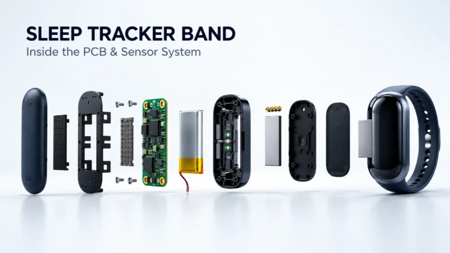

Build a sleep-tracking wristband around the requirements that matter in production: stable PPG sensor alignment, low-power electronics, compact PCB or flex construction, controlled component sourcing, and repeatable functional testing. Highleap Electronics supports customer-designed wearable PCB and PCBA projects from prototype builds through production planning.
Whether your product is a screenless recovery band or a fitness tracker with overnight monitoring, the manufacturing plan must connect the electrical design, optical window, enclosure, battery, charging interface, firmware test mode, and final assembly sequence. The goal is a repeatable module that can be integrated and validated in the finished wearable—not simply a small board with components attached.
Sleep Tracker Band Architectures and PCB Requirements
Sleep-tracking wearables do not all use the same electronics layout. PCB outline, sensor stack, battery capacity, antenna location, and assembly sequence depend on the measurements the product is designed to collect and how the device is worn.
| Architettura | Elettronica tipica | Considerazioni sulla produzione |
|---|---|---|
| Screenless sleep band | PPG sensor, MCU or BLE SoC, memory, battery management | Low profile, standby current, compact enclosure, reliable app synchronization |
| Recovery or HRV band | PPG front end, IMU, optional temperature sensor, BLE | Optical geometry, motion-sensor orientation, repeatable test firmware |
| SpO2-capable wearable | Multi-wavelength LEDs, photodetector and analog front end | Optical isolation, LED drive control, window and skin-contact tolerances |
| Fitness tracker with sleep mode | Sleep sensors plus display, haptic driver or user-interface circuits | Peak-current demand, mechanical interfaces, more power-state tests |
| Strap-integrated design | Rigid sensor module with flex tail or distributed electronics | Flex routing, bend limits, strain relief, connectors and enclosure sequence |
A screenless product may free board area and energy otherwise used by a display, but it does not automatically guarantee longer battery life. Runtime still depends on sensor duty cycle, LED current, radio activity, firmware behavior, battery capacity, and leakage current.
What should be decided before requesting a quote?
Confirm whether the quote covers bare PCB fabrication, assembled PCBA, component sourcing, programming, functional testing, or mechanical integration. Identify the build stage—engineering prototype, design validation, pilot production, or recurring production—because quantity, test coverage, documentation, and acceptance criteria may differ.
PPG and SpO2 Sensor Placement and Optical Assembly
Photoplethysmography (PPG) uses light emitters and a photodetector to measure changes in reflected light associated with blood-volume changes near the skin. Depending on the design, optical channels may use green, red, or infrared light. SpO2 functionality requires an appropriate sensor configuration and a validated measurement system; the presence of red and infrared LEDs alone does not establish accuracy.
The PCB, sensor package, optical barrier, window, gasket, and enclosure form one tolerance chain. A correctly soldered sensor can still perform poorly if the window is misaligned, the gasket allows optical leakage, or the enclosure changes the intended sensor-to-skin spacing.
- Orientamento del sensore: Define package orientation in the assembly drawing and verify it during inspection or test.
- Optical separation: Use the specified light barrier and window geometry to limit direct light leakage between emitter and detector.
- Height and coplanarity: Control sensor height relative to the PCB, lens or window, gasket, and skin-facing surface.
- Pulizia: Prevent flux residue, adhesive, dust, fingerprints, and protective-film debris from contaminating the optical path.
- Rumore elettrico: Review switching regulators, radio bursts, LED drive currents, and charging circuits for possible interference with the analog front end.
- ripetibilità: Define fixture-based checks and measurable limits instead of relying on visual inspection alone.
Can a PCBA supplier validate sleep-stage or HRV accuracy?
Not from assembly inspection alone. A manufacturing partner can verify assembly quality, sensor communication, defined electrical behavior, and repeatable fixture-based optical checks where suitable equipment and limits are provided. Sleep-stage classification, HRV interpretation, recovery scores, and health-related claims depend on the complete hardware, firmware, algorithm, wear conditions, and validation method. Those system-level outcomes must be established by the product owner using an appropriate validation plan.
IMU and Temperature Sensor Integration
An inertial measurement unit (IMU) can provide movement data, while a temperature sensor may measure device or skin-adjacent temperature depending on the design. The meaning of these signals depends on sensor placement, calibration, firmware, and intended use.
- IMU axis definition: Document orientation relative to the band coordinate system and confirm axis mapping in firmware and test procedures.
- Mechanical coupling: Keep sensor mounting and enclosure structure consistent so looseness or vibration does not unpredictably affect measurements.
- Posizionamento della temperatura: Consider heat from the MCU, power converter, radio, battery, and charging interface. Placement should match the quantity being measured.
- Comunicazione del sensore: Test I2C, SPI, interrupt, or other interfaces according to the released design.
- Controllo variabile: Record approved part numbers and revisions. A substitute may differ in address, pinout, package, calibration, or firmware support.
Some products add electrodes for bioimpedance or ECG-related functions. These introduce additional analog, contact, safety, and validation requirements and should be specified separately in the RFQ.
Low-Power Design and Battery-Life Verification
Overnight operation is a system-level requirement. A schematic review can identify likely power consumers, but cannot prove actual runtime by itself. Firmware state transitions, sensor schedules, LED pulse current, BLE synchronization, regulator quiescent current, battery characteristics, and circuit leakage all affect energy use.
| Stato operativo | Cosa misurare | What the RFQ should specify |
|---|---|---|
| Deep sleep or standby | Supply current after entering the defined low-power state | Firmware entry procedure, settling time, current limit, instrument setup |
| Rilevamento attivo | Current with intended PPG, IMU, and temperature settings | Sensor configuration, LED drive, sampling rates, allowed range |
| BLE synchronization | Average and peak current during defined radio activity | Test mode, radio settings, measurement window |
| ricarica | Charging behavior and relevant battery/system measurements | Approved cell, charger configuration, contact arrangement, pass limits |
For Bluetooth connectivity, review Scheda Bluetooth requirements, including antenna keep-out, ground arrangement, enclosure effects, and RF test access. Charging and protection circuitry should follow the selected cell manufacturer’s limits and the approved design; see PCB di gestione della batteria considerazioni.
Do not specify battery-life acceptance without defining workload and conditions. State the firmware version, sensor configuration, radio activity, battery type and condition, ambient conditions, and measurement method. The OEM should correlate production current checks with system-level runtime testing.
Rigid PCB, Flex PCB, and Rigid-Flex Options
The mechanical architecture determines whether a compact rigid board is sufficient or flexible circuitry is needed to connect sensors, charging contacts, or electronics distributed through the strap. The best option satisfies enclosure, electrical, reliability, and assembly requirements without unnecessary process complexity.
- PCB rigido: Often suitable when electronics fit within one sensor pod; it can simplify component placement and board support.
- PCB flessibile: Can route signals through curved or moving sections. Define bend radius, copper type, coverlay, stiffener locations, and whether bending is static or dynamic. See produzione di PCB flessibili.
- PCB rigido flessibile: Can combine rigid component areas with flexible interconnects and reduce some connectors. Review stackup, transition geometry, stiffeners, and handling early. See produzione di PCB rigido-flessibili.
- Scheda PCB HDI: May be appropriate when fine-pitch packages or dense routing require microvias or other high-density features. Select it based on actual routing and reliability needs, not simply because the device is small. See Produzione di PCB HDI.
Very small passives and fine-pitch packages may save area but narrow placement, solder-paste, inspection, and rework windows. Review package availability, pad geometry, stencil design, and inspection access before release.
What mechanical files help the factory review a wearable PCB?
Provide PCB or flex fabrication data, a dimensioned outline, stackup, component placement data, assembly drawings, and relevant enclosure or optical-window drawings. For flex and rigid-flex, include bend zones, stiffener details, coverlay openings, and handling constraints. Gerber files alone may not reveal sensor alignment or enclosure interference risks.
PCB Assembly, Component Sourcing, and Process Control
Wearable PCBA quality depends on component placement, solder-joint integrity, optical cleanliness, traceability, and the ability to test electronics before the unit is sealed.
- Engineering and DFM review: Check fabrication data, stackup, footprints, polarity, clearances, flex handling, test points, and assembly drawings.
- BOM and sourcing review: Confirm manufacturer part numbers, approved alternates, lifecycle status, package variants, and customer-mandated sources. Do not substitute optical sensors, IMUs, batteries, or RF components without approval.
- Fabbricazione PCB: Build the specified rigid, flex, or rigid-flex board to released data. State controlled-impedance and special-via requirements where applicable.
- Assemblaggio SMT: Use the approved stencil, placement program, reflow profile, and handling method for the selected components and board construction.
- Ispezione: Apply AOI and other methods based on package type and access. Hidden solder joints may need another inspection method when justified by the package and acceptance plan.
- Programming and electrical test: Load the authorized firmware or test image and run agreed checks.
- Optical and mechanical integration: Complete window, gasket, adhesive, or enclosure operations in the defined sequence, preventing contamination and misalignment.
- tracciabilità: Record agreed lot, revision, test, and serialization information.
Highleap Electronics fornisce Assemblaggio PCB and approvvigionamento di componenti elettronici support for customer-defined projects. Confirm whether the quote includes bare boards, consigned components, turnkey PCBA, programming, test, or mechanical integration.
Inspection methods should match the failure mode
- AOI: Can check visible component presence, polarity, orientation, and solder features within system capability; it does not prove sensor accuracy or detect every hidden-joint defect.
- Raggi X: May be appropriate for packages with hidden solder joints when justified by package type and risk assessment.
- Test elettrico: Confirms defined electrical conditions or connections according to test method and coverage.
- Test funzionale: Exercises behaviors that can be measured repeatably with a fixture, test firmware, and clear limits.
See AOI nel PCBA. Agree on inspection coverage before production; no single method replaces a risk-based quality plan.
Production Testing Before Enclosure Sealing
Where practical, test the board and sensors before permanent sealing makes rework or probing difficult. The production test should distinguish measurable assembly defects from algorithm or system behavior that requires OEM-level validation.
| Area di prova | Example checkpoint | Customer input required |
|---|---|---|
| Binari di alimentazione | Check supply rails and current consumption | Test points, voltage windows, operating state, current limits |
| PPG subsystem | Read sensor identity and verify LED drive or detector response using an agreed fixture | Sensor configuration, fixture method, pass/fail limits |
| IMU and temperature | Verify communication, axis mapping, and plausible output | Expected orientation, settings, acceptable range |
| BLE | Verify test-mode communication, device identity, or specified RF checks | Firmware image, test procedure, RF criteria if required |
| ricarica | Check contact detection and defined charging behavior | Approved cell, charger limits, fixture, requirements |
| Optical/mechanical interface | Check alignment, cleanliness, and repeatable fixture response where defined | Window drawing, gasket details, fixture, validated limits |
| Tracciabilità | Associate results with the unit or production lot | Serial format, data fields, retention period, report format |
Highleap può supportare soluzioni definite dal cliente test funzionali when the fixture, firmware, measurement method, and acceptance limits are agreed. If per-unit optical calibration is required, specify who supplies the algorithm, calibration equipment, data format, and approval criteria.
DFM Risks to Resolve Before Ordering
- Incomplete fabrication package: Missing stackup, drill data, flex details, impedance requirements, or revision can make the quote ambiguous.
- Unclear sensor-window tolerances: A PCB drawing alone may not define the relationship among sensor, barrier, window, gasket, and skin-contact surface.
- Unapproved BOM substitutions: Similar-looking sensors or power ICs may differ in package, pinout, optical behavior, firmware support, or availability.
- No defined test mode: Without firmware commands, test pads, or fixture access, production testing may be slower or less repeatable.
- Unspecified current limits: “Low power” is not an acceptance criterion. Define state, setup, settling time, and allowed current.
- Flex fatigue or strain: Dynamic bending, sharp transitions, poor strain relief, or unsupported flex areas can create reliability risks.
- Late enclosure integration: Clips, adhesive, seals, and charging contacts may obstruct test access or interfere with the sensor stack.
- Unclear production scope: Bare PCB, PCBA, programming, optical testing, battery installation, sealing, and final assembly are different deliverables.
For prototypes, record open issues and engineering changes rather than assuming the first assembled unit is production-ready. Before pilot or volume production, freeze the applicable PCB revision, BOM, firmware/test version, assembly instructions, and acceptance criteria.
Review Your Sleep Tracker Band PCB Before the Next Build
Send Gerber or ODB++ data, BOM, pick-and-place file, board stackup, optical-window or enclosure drawings, target quantity, and required test limits. Highleap can review the manufacturing package and clarify the scope for PCB fabrication, component sourcing, assembly, and agreed production testing.
Richiedi un preventivo per PCB Discuss PCBA Requirements
For an early-stage design, include the files available and identify what remains under development. A preliminary review can clarify missing information before the quotation is finalized.
Sleep Tracker PCB and PCBA RFQ Checklist
Use this checklist to help the manufacturing team quote the intended build rather than make assumptions about the product configuration.
| Articolo RFQ | Cosa fornire | Perché è importante |
|---|---|---|
| Dati di fabbricazione | Gerber or ODB++, drill files, stackup, thickness, copper weight, finish, impedance notes if applicable | Defines bare-board construction |
| Dati di assemblaggio | BOM with manufacturer part numbers, pick-and-place file, assembly drawing, polarity notes, PCB revision | Supports sourcing, placement programming, and assembly planning |
| Pila ottica | Sensor part numbers, LED configuration, window/gasket drawings, tolerances, fixture information | Defines alignment and measurable optical checks |
| Progettazione meccanica | Enclosure dimensions, strap curvature, flex bend zones, stiffeners, connectors, charging contacts | Identifies fit, handling, strain, and test-access risks |
| Power and firmware | Battery specification, charging circuit, firmware/test image, operating states, current limits | Enables repeatable power and functional checks |
| Test e qualità | AOI/X-ray/electrical/FCT scope, fixtures, pass/fail limits, serialization, report format | Clarifies acceptance and production records |
| Dettagli commerciali | Prototype and forecast quantities, target schedule, destination, sourcing constraints, packaging | Supports a realistic quotation and production plan |
If files are incomplete, identify the current revision and provisional details. This helps distinguish a budgetary estimate from a firm quotation based on released manufacturing data.
Domande frequenti
Can Highleap manufacture a PCB for a sleep tracker band?
Highleap can review customer-provided design and manufacturing data for wearable PCB fabrication and PCBA requirements. Feasibility depends on board construction, component packages, sourcing constraints, assembly scope, and required testing. Submit the design package for a project-specific review.
Can you supply both the PCB and assembled electronics?
PCB fabrication and assembly can be quoted together when the required data and scope are available. Specify whether you need bare boards, consigned components, turnkey sourcing, programming, functional testing, or mechanical operations.
What files are needed for a sleep tracker PCBA quote?
Start with Gerber or ODB++ files, drill data, a BOM with manufacturer part numbers, pick-and-place data, and an assembly drawing. Add stackup, flex details, enclosure and optical-window drawings, firmware/test instructions, quantity, and acceptance criteria where available.
Can the factory test PPG sensors before the band is sealed?
Yes, if the project provides a suitable test method and measurable limits. Checks may include sensor communication, LED drive, detector response, or a fixture-based optical test. This is not the same as validating sleep-stage or health-metric accuracy.
Should I use rigid, flex, or rigid-flex PCB?
The choice depends on enclosure, available space, bend requirements, component placement, interconnect strategy, and expected mechanical life. Review mechanical drawings and bend conditions before selecting the construction.
Can you guarantee overnight battery life?
Battery life depends on the complete design, cell capacity and condition, firmware, LED drive, sampling schedule, radio activity, power-management components, and use conditions. A PCBA supplier can measure agreed current states, but runtime validation requires a defined system workload and method.
Can a PCB assembly factory validate SpO2, HRV, or sleep-stage accuracy?
Assembly and fixture testing can confirm defined electrical and sensor behaviors. Accuracy claims require system-level validation using appropriate reference methods and conditions. The OEM remains responsible for algorithms, product claims, and applicable regulatory or clinical validation.
What information helps reduce prototype lead-time risk?
Provide a clearly identified design revision, complete fabrication and assembly files, approved component sources, substitution rules, firmware/test instructions, and acceptance criteria. Late BOM changes, unavailable parts, missing mechanical details, and undefined tests can affect the schedule.

Messaggi consigliati

Preventivo e stackup PCB RT duroid 6002
Questa pagina è responsabile dell'attività di quotazione e definizione dello stackup...
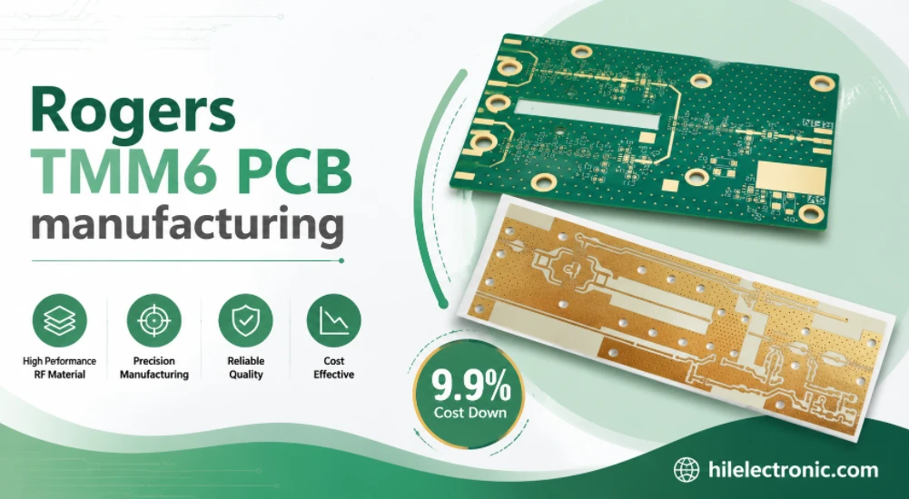
Produzione di PCB per filtri TMM6
Indice dei contenuti Perché i progettisti di filtri a microonde utilizzano...
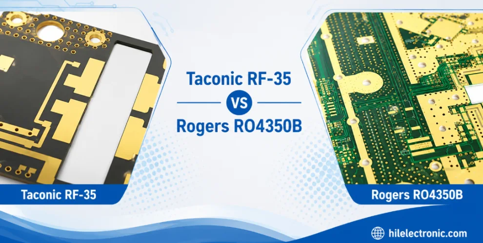
Taconic RF 35 vs RO4350B PCB
Indice RF-35 vs RO4350B Approvvigionamento e...
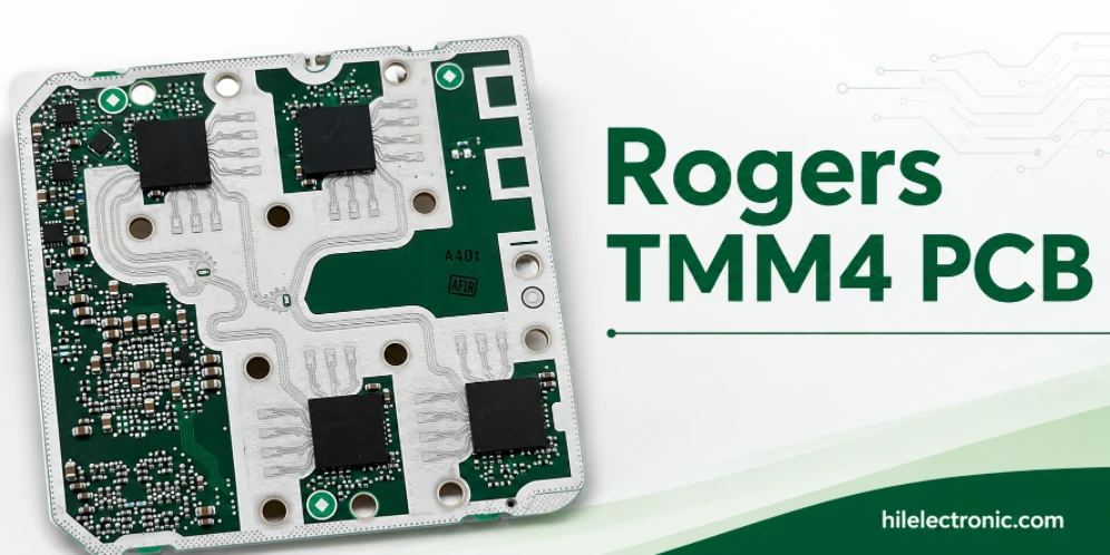
Produzione di PCB per filtri TMM4
La produzione del PCB del filtro TMM4 è controllata da...
Come ottenere un preventivo per i PCB
Eseguiremo un'analisi DFM/DFA per te e ti invieremo un report. Puoi caricare i tuoi file in modo sicuro tramite il nostro sito web. Per poterti fornire un preventivo, abbiamo bisogno delle seguenti informazioni:
-
- Specifiche Gerber, ODB++ o .pcb.
- Elenco BOM se è necessario l'assemblaggio
- Quantità
- Tempo di svolta
Per i servizi PCBA, vi preghiamo di fornire la vostra distinta base (BOM) e le istruzioni di assemblaggio specifiche. Offriamo anche analisi DFM/DFA per ottimizzare i vostri progetti in termini di producibilità e assemblaggio, garantendo un processo produttivo fluido.