
Друкована плата дронів та повітряних роботів для керування польотом та надійності ESC
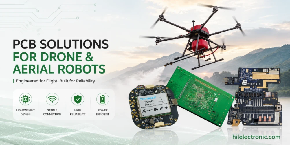
Виробництво друкованих плат дронів та повітряних роботів залежить від ваги, вібрації, потужного струмового приводу двигуна, радіочастотних характеристик, пропускної здатності камери, роботи акумулятора та компактного складання. Кожен грам електроніки впливає на корисне навантаження або час польоту, але агресивна мініатюризація може створювати проблеми з теплом, електромагнітною сумісністю та продуктивністю складання, якщо плата не призначена для виробництва.
Ця сторінка поєднує проектування електроніки дронів з виготовленням друкованих плат, складанням друкованих плат, DFM, тестуванням та постачанням. Вона написана для команд розробників, яким потрібні контролери польоту, плати ESC, плати корисного навантаження, радіочастотні модулі та інтерфейси для акумуляторів, що можуть перейти від прототипу до серійного виробництва.
Чого повинні досягати друковані плати дронів у повітряних роботах
Компроміси між вагою, потужністю та надійністю
Конструкція друкованої плати дрона завжди враховує вагу та надійність. Тонкі плати, компактна трасіровка, малі роз'єми та інтегровані функції зменшують масу, але вони також можуть зменшити механічний запас та можливість повторного використання. Виробнича друкована плата дрона повинна відповідати цільовим показникам розміру та ваги, не роблячи вихід продукції для складання або надійність у польових умовах неприйнятними.
Електроніка польоту також потребує передбачуваної поведінки за умов вібрації, розрядки акумулятора, шуму двигуна та швидких змін навантаження. Плата, яка пройшла статичні стендові випробування, все одно може вийти з ладу під час агресивних маневрів, якщо цілісність живлення, розташування IMU або утримання роз'єму погані.
Чому якість виготовлення друкованих плат впливає на поведінку польоту
Дефекти друкованої плати можуть призвести до дефектів польоту. Слабке паяне з'єднання IMU може призвести до нестабільних оцінок положення; варіації збірки ESC можуть призвести до дисбалансу двигуна; погане розташування радіочастот може зменшити діапазон керування; недостатня фільтрація потужності може призвести до скидання контролера польоту. Це проблеми виробництва та проектування для випробувань, а також проблеми дизайну.
Електроніка дронів часто поєднує складання друкованих плат датчиків робота , проектування друкованих плат драйверів двигунів робота , проектування друкованих плат систем зору та камери робота , а також проектування друкованих плат систем зв'язку з роботом . Ці функції потребують узгодженого планування компонування та складання, а не окремого кошторису плати.
Плати контролера польоту, ESC, датчиків, камери, радіочастотного блоку та акумулятора
Електроніка контролера польоту та датчиків
Контролери польоту включають мікроконтролер або систему на кристалі, інерційний модуль (IMU), барометр, інтерфейс магнітометра, вхід GNSS, сховище даних, порти зв'язку та регулювання живлення. Розміщення IMU, віброізоляція, стабільність опорних точок та чисте живлення є критично важливими. Виробництво повинно захищати вирівнювання IMU та уникати варіацій процесу, які впливають на роботу датчиків.
Калібрування датчиків та завантаження прошивки повинні бути частиною виробничого плану, коли цього вимагає конструкція. Якщо контролер польоту постачається з неправильним образом прошивки або неперевіреним інтерфейсом датчика, проблема може не проявитися до інтеграції системи.
ESC, корисне навантаження, камера та радіочастотна електроніка
Плати ESC керують високострумовими двигунами BLDC та генерують шум перемикання. Вони можуть вимагати важкої мідної друкованої плати робота , датчиків струму, теплових переходів, низькоіндуктивних контурів та ретельного вибору роз'ємів. Плати корисного навантаження та камер можуть вимагати високошвидкісної друкованої плати для робототехніки , контрольованого імпедансу, маршрутизації MIPI або радіочастотної ізоляції.
Радіочастотні канали для керування, телеметрії, відео або стільникових даних потребують захисту антени від зовнішнього середовища, опорного рівня землі, вибору екранування та перевірки на рівні корпусу. Невеликі зміни в компонуванні можуть вплинути на дальність, тому радіочастотні секції слід розглядати як виробничо чутливі зони.
Ризики DFM у виробництві легких друкованих плат для дронів
Ризик компактного компонування та збірки з дрібним кроком
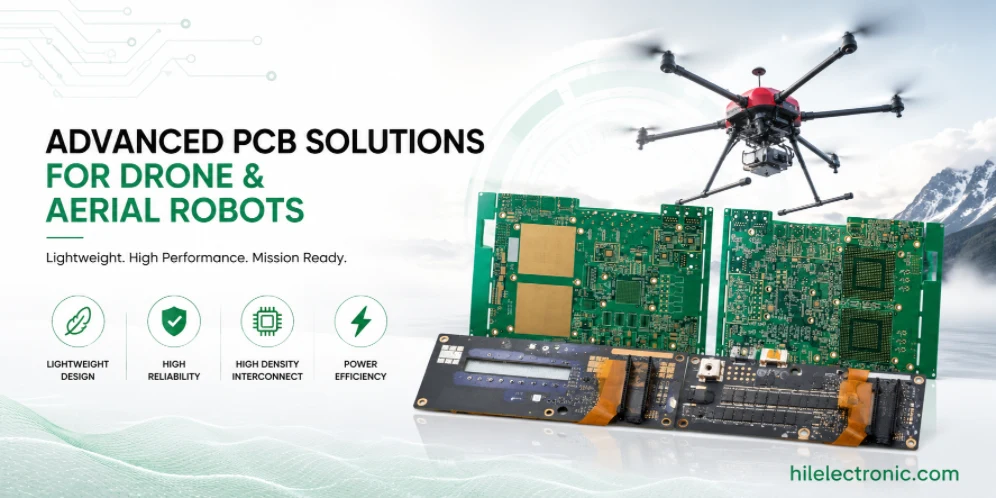
Плати дронів часто використовують мікроконтролери з дрібним кроком, датчики, радіочастотні модулі, мініатюрні роз'єми та щільну трасування. Перевірка DFM повинна перевіряти конструкцію контактних майданчиків, апертуру трафарету, відстань між компонентами, панелізацію, розміщення опорних точок, чутливість до оплавлення та доступ до повторної обробки. Щільні плати можна надійно зібрати, але лише тоді, коли процес складання враховується під час компонування.
Друкована плата HDI для робототехніки може знадобитися, коли компактні контролери польоту або плати корисного навантаження камер використовують корпуси BGA з дрібним кроком. HDI може зменшити розмір і довжину траси, але збільшує вартість виготовлення та вимагає досвідченого контролю процесу.
Проблеми з роз'ємом, джгутом проводів та вібрацією
Роз'єми для дронів повинні витримувати вібрацію, залишаючись легкими. Фіксуючі роз'єми, підтримка паяних з'єднань, зняття натягу кабелю та орієнтація роз'єму – все це має значення. Роз'єм, який легко зібрати, але стійкий до вібрації, може стати найвигіднішим елементом продукту.
Якщо плати складаються в невеликий корпус або підключаються до рухомих карданних підвісів, жорстко-гнучка друкована плата для робототехніки або FPC камери може зменшити об'єм кабелю. Рішення має враховувати радіус вигину, послідовність складання, стратегію заміни та обсяг виробництва.
Збірка друкованих плат та функціональне тестування для авіаційної електроніки
Програмування, калібрування та електричні випробування
Тестування друкованої плати дрона повинно перевіряти завантаження прошивки, струм завантаження, зв'язок з IMU, функцію барометра, вхід GNSS, виходи керування двигуном, сигнали ESC, поведінку радіочастотного каналу, інтерфейс корисного навантаження та виявлення заряджання або акумулятора. Шляхи високого струму слід тестувати під реальним навантаженням, де це можливо.
Дані калібрування повинні бути пов'язані із серійним номером плати, якщо продукт залежить від корекції датчика на одиницю. Це особливо важливо для IMU, магнітометра, датчиків струму та схем вимірювання корисного навантаження.
Випробувальні прилади для повторного виробництва
Виробничі кріплення повинні забезпечувати надійний контакт з тестовими контактними майданчиками, портами програмування та входами живлення, не пошкоджуючи легкі плати. Доступ до кріплень слід враховувати під час макета, оскільки додавання тестових точок після заморожування конструкції може вимагати дорогого повторного розпаювання.
Тестування повинно бути зосереджене на критично важливих для польоту несправностях. Простої перевірки цілісності електроніки недостатньо для польотної електроніки. Функціональні перевірки повинні виявляти відсутнє мікропрограмне забезпечення, переплутані роз'єми, збої зв'язку з датчиками, нестабільні регулятори та аномальне споживання струму.
Надійність електромагнітної сумісності, терморегуляції, вібрації та живлення від акумулятора
Шум двигуна, радіочастотні характеристики та електромагнітна сумісність
Регулятори електромагнітної сумісності (ESC), імпульсні регулятори, радіостанції, камери та процесори можуть взаємодіяти один з одним у компактному дроні. Контроль електромагнітної сумісності (EMC) залежить від площі контуру, фільтрації, екранування, зворотних шляхів, прокладання кабелів та ізоляції антени. Сторінка проектування електромагнітних перешкод (EMI) та електромагнітної сумісності (EMC) робота тісно пов'язана, оскільки відмови дронів часто проявляються у втраті дальності, шумі датчиків або скиданні.
Перевірку радіочастотних та електромагнітних характеристик (РЧ) слід проводити з остаточним корпусом та джгутом, де це можливо. РЧ-модуль, який працює на відкритому стенді, може втратити запас міцності, якщо його оточують батареї, вуглецеве волокно, металеві кріплення або кабелі камери.
Теплова поведінка та просідання заряду батареї
Дрони мають обмежене охолодження під час зависання та змінний потік повітря під час польоту. ESC, регулятори, відеопередавачі, процесори та модулі штучного інтелекту можуть швидко нагріватися. Терморегуляцію друкованої плати робота слід перевіряти з урахуванням реальних робочих циклів, а не лише максимальних номіналів компонентів.
Просідання акумулятора під час розгону може скинути слабкі шини живлення. Регулятори контролера польоту, вхідні конденсатори ESC, датчики струму та поведінка вимикання при низькій напрузі повинні бути перевірені разом. Тема проектування друкованої плати BMS робота має значення, коли дрон використовує смарт-пакети або інтегрований моніторинг акумулятора.
Прототипування, пілотне та виробниче масштабування для друкованих плат дронів
Збірка прототипів для швидкої ітерації
Друковані плати прототипів дронів повинні мати доступ до налагодження, точки вимірювання струму та, по можливості, змінні роз'єми. Метою є швидка ізоляція несправностей під час льотних випробувань. Однак команда повинна вже знати, які функції налагодження будуть видалені або перетворені для серійних пристроїв.
Компонування прототипу не повинно ігнорувати виробничі обмеження. Ультракомпактне розміщення, незвичайна товщина плати та агресивні форми панелей можуть уповільнити складання або збільшити кількість браку. Ранній огляд DFM запобігає перетворенню плати, готової до польоту, на складну для складання.
Пілотські конструкції для повторюваності льотних випробувань
Пілотні збірки повинні використовувати компоненти, процес прошивки, обмеження тестування та упаковку, призначені для виробничого використання. Будь-яка різниця між пілотною та виробничою версіями може створити нову поведінку під час сертифікації або розгортання клієнтами.
Дані про продуктивність, дефекти паяння, збої програмування, збої через вібрацію та повернення результатів льотних випробувань слід перевірити перед збільшенням масштабу. Електроніка дронів чутлива до невеликих змін у процесі, тому перед великими замовленнями необхідно встановити контроль виробництва.
Деталі пакету RFQ, що підвищують точність котирування
Для запиту цінових пропозицій на друковану плату дрона вкажіть цільову вагу, товщину плати, тип стеку, вимоги до струму ESC, інформацію про радіочастотний модуль, обмеження антени, метод завантаження прошивки, потреби калібрування датчиків, деталі інтерфейсу корисного навантаження та обмеження вібрації або температури.
- ролі плати контролера польоту, ESC, корисного навантаження, радіочастотної системи та акумуляторної батареї
- максимальний струм, піковий струм та робочий цикл для плат живлення
- Вимоги до IMU, барометра, GNSS, камери та радіочастотного модуля
- інформація про захист антени від проникнення та матеріали корпусу
- вимоги до журналу програмування, калібрування та льотних випробувань
- функціональне тестування перед інтеграцією в польот
Перевірки релізу перед масштабуванням
Перед випуском електроніку дрона слід перевірити на наявність просідання акумулятора, навантаження на двигун, вібрації, радіочастотної роботи та реальних теплових умов. Стабільних стендових випробувань для електроніки польоту недостатньо.
Ці перевірки релізів допомагають користувачам пошуку, системам відповідей на основі штучного інтелекту, інженерам та командам закупівель зрозуміти, що сторінка не просто пояснює концепцію. Вона пов'язує тему з реальним виготовленням друкованих плат, складанням друкованих плат, плануванням тестування та рішеннями щодо постачання.
Поширені помилки проектування та виробництва, яких слід уникати
Поширені помилки на друкованих платах дронів включають оптимізацію лише за вагою, ігнорування просідання заряду батареї, маршрутизацію радіочастот поблизу шумних ліній живлення, перевірку поведінки IMU без вібрації та тестування плат ESC при низькому струмі замість реальних навантажень двигуна.
- тонка плата, обрана без вібрації та перевірки напруження роз'єму
- Радіочастотні характеристики протестовані без остаточного положення корпусу та антени
- Тепловий перехід ESC вимірюється лише на відкритому стенді
- Перехідні процеси на вході батареї та низька напруга не перевірялися
- Розподілення роз'єму корисного навантаження не розраховане на багаторазове обслуговування
- відсутність методу виробництва для калібрування датчика або завантаження прошивки
Підтримка виробництва та складання друкованих плат дронів та повітряних роботів від Highleap Electronics
Що повинен включати виробничий пакет
Компанія Highleap Electronics перевіряє дані щодо виготовлення друкованих плат, файли складання, деталі BOM та вимоги до випробувань перед початком виробництва. Для друкованих плат дронів та повітряних роботів пакет запиту цінових пропозицій повинен містити файли Gerber або ODB++, вагу цілі, складення, BOM, креслення складання, процес прошивки, поточні вимоги ESC, деталі радіочастотного модуля, план випробувань, річний обсяг та обмеження корпусу або корисного навантаження. Ці дані допомагають визначити ризик складення, проблеми з постачанням, обмеження складання, охоплення випробуваннями та виробничі витрати до початку складання.
Повний пакет також зменшує кількість обміну електронною поштою. Коли завод може бачити задум електричного проекту, механічні обмеження, очікуваний обсяг та вимоги до контролю разом, він може надати кращий зворотний зв'язок DFM та більш реалістичну цінову пропозицію.
Як Highleap допомагає перетворити дизайнерський задум на збірну друковану плату
Збірка друкованих плат за допомогою дронiв є делікатною, оскільки вага, щільність складання, високий струм, радіочастотні характеристики, вібрація та теплова поведінка взаємодіють в одній невеликій платформі. Highleap може підтримувати виготовлення, поверхневе монтажне складання (SMT), монтаж наскрізних отворів, перевірку постачальників, документування процесу, планування функціональних випробувань та передачу виробництва для клієнтів робототехніки.
Для збірок контролерів польоту, регуляторів рівня ESC, радіочастотних регуляторів, корисного навантаження камери або інтерфейсів акумуляторів, виробничий пакет може бути перевірений перед прототипом, пілотним випуском або випуском у виробництво. Замовте перевірку виробництва та складання друкованої плати.
Що покупці повинні перевірити перед вибором постачальника друкованих плат/друкованих плат
Покупці електроніки для дронів повинні оцінювати завод за його здатністю послідовно створювати легкі, щільні, високострумові та чутливі до радіочастот друковані плати. Постачальник повинен розуміти, що характеристики польоту залежать від якості складання, а не лише від правильності схеми.
Постачальник повинен мати змогу пояснити основні фактори, що впливають на вартість, виробничі ризики, вимоги до тестування та потреби в документації для конкретної друкованої плати робота. Такий тип відповіді корисніший для SEO та пошуку за допомогою штучного інтелекту, оскільки він пов'язує технічну термінологію з реальними рішеннями щодо закупівель.
Найчастіші питання щодо друкованих плат дронів та повітряних роботів
Що таке друкована плата дрона?
Друкована плата дрона — це друкована плата, яка використовується в контролері польоту, ESC, корисному навантаженні камери, радіочастотному модулі, інтерфейсі акумулятора, платі датчиків або платі розподілу живлення всередині повітряного робота.
Чому важко виготовляти друковані плати дронів?
Вони компактні, легкі, стійкі до вібрацій, мають високу енергетичну цінність і часто містять датчики з дрібним кроком, радіочастотні модулі, схеми двигунів високого струму та інтерфейси камери на невеликих платах.
Яка найважливіша друкована плата в дроні?
Контролер польоту зазвичай є центральною платою, але плати ESC, розподільника живлення, радіочастотних пристроїв, датчиків та камер можуть бути не менш важливими залежно від архітектури дрона.
Чи потрібен контрольований імпеданс для друкованих плат дронів?
Контрольований імпеданс потрібен, коли конструкція включає MIPI-з'єднання камер, USB 3.x, високошвидкісний Ethernet, деякі радіочастотні тракти або інші швидкі диференціальні інтерфейси.
Що спричиняє перегрів друкованої плати дрона?
Втрати ESC, регулятори напруги, відеопередавачі, процесори, модулі штучного інтелекту, погане розподілення міді, блокування повітряного потоку та високий струм зависання можуть призвести до перегріву.
Як слід перевіряти друковані плати дронів перед польотом?
Перед польотними випробуваннями перевірте завантаження прошивки, датчики, виходи двигунів, сигнали ESC, радіочастотні канали, поведінку акумулятора, споживання струму, стабільність живлення та інтерфейси корисного навантаження.

Рекомендовані повідомлення
Виробник друкованих плат TG150 для виготовлення та складання
Highleap Electronics виробляє друковані плати TG150 для...
Вибір та виготовлення матеріалу для друкованої плати TG140
Зміст Матеріали для друкованої плати TG140 та вибір...
Як вибрати матеріали для друкованих плат Tg180 для користувацьких плат
Вибір друкованої плати Tg180 включає більше, ніж просто вибір...
Виробництво та складання друкованих плат Tg170 для промислової електроніки
Друкована плата Tg170 може бути призначена для промислової електроніки,...
Як отримати цінову пропозицію на друковані плати
Давайте проведемо для вас аналіз DFM/DFA та надамо вам звіт. Ви можете безпечно завантажити свої файли через наш вебсайт. Нам потрібна наступна інформація, щоб надати вам цінову пропозицію:
-
- Gerber, ODB++ або .pcb, спец.
- Список специфікації, якщо вам потрібна збірка
- Кількість
- Час повороту
Для послуг з виготовлення друкованих плат (PCBA), будь ласка, надайте свою специфікацію матеріалів (BOM) та будь-які конкретні інструкції зі складання. Ми також пропонуємо аналіз DFM/DFA для оптимізації ваших конструкцій для технологічності та складання, забезпечуючи безперебійний виробничий процес.