
IT-170GT PCB Fabrication for Multilayer Boards
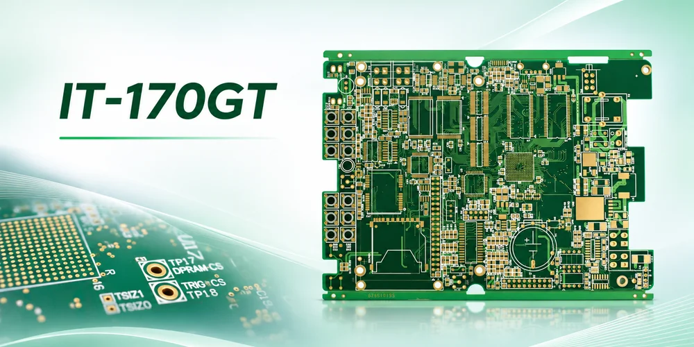
Illustration of a multilayer PCB with plated holes.
ITEQ IT-170GT is a halogen-free, high-Tg laminate and prepreg system for rigid multilayer PCBs. The current datasheet lists a 185°C glass transition temperature by DSC and a 150°C maximum operating temperature for laminate thickness of at least 0.63 mm. For a thick board with plated connector holes, the material is one part of the reliability decision. The drill geometry, inner-layer bond and copper barrel still have to survive the assembly and service conditions.
Read the thermal numbers as separate design inputs
Thermal qualification has three different questions: how the material expands as it heats, what rating applies to the specified construction, and how the fabricated and populated board behaves through its actual temperature history. Those questions require different evidence.
| Στοιχείο φύλλου δεδομένων | Αναφερόμενο αποτέλεσμα | Πως να το χρησιμοποιήσεις |
|---|---|---|
| Tg (DSC) | 185 ° C | Identifies the glass transition by the stated method. It is not the continuous use rating. |
| Μέγιστη θερμοκρασία λειτουργίας | 150°C at laminate thickness ≥0.63 mm | Read the UL 746 entry with its thickness condition. Do not infer it from overall board thickness or extend it to a populated product. |
| 50–260°C Z-axis expansion | 2.2% at 58% resin content; 1.7% at 48% | Compares expansion of the tested laminate constructions over the stated interval. |
| Td and delamination time | Td 380°C at 5% mass loss; T260 and T288 each >60 min | Distinct laboratory tests. These are not reflow limits or cycle counts. |
| Dk and Df at 10 GHz | 3.9 και 0.0095 | 55% resin content, IPC-TM-650 2.5.5.13; a separate specimen basis from the expansion entries. |
Πηγή: ITEQ IT-170GT datasheet, Rev. 1.0-26. The CCL row identifies IT-170GT; the prepreg row lists IT-170GTB. Verify construction codes and the applicable safety recognition when releasing the purchase specification.
What does the difference in resin content change?
The 58% specimen shows 0.5 percentage points more through-thickness expansion than the 48% specimen over the published interval. A multilayer board can combine several core and prepreg constructions, with copper patterns that constrain movement. The difference signals that stack composition matters; it does not give the local strain in a plated hole. Specify individual dielectric builds, copper weights and required resin fill. Do not simply select a lower resin content to reduce expansion if it leaves too little resin to fill the etched relief.
Design the connector hole for both fabrication and fit
In a thick multilayer board, the resin and reinforcement expand through the thickness during heating while the bonded copper barrel is constrained. The resulting stress can accumulate through repeated excursions. A thin section of copper, a drill defect or a poor connection to an internal land can become the local weakness. The inspection must therefore represent the hole family most at risk, which may be a smaller plated hole on the same panel rather than the main connector hole.
Hypothetical connector review. A 2.40 mm board calls for a 0.30 mm finished plated hole. If the proposed production drill diameter is 0.38 mm, the nominal board-thickness-to-drill ratio is about 6.3:1. Dividing by the finished diameter gives 8.0:1, a different quantity. The drill value helps review plating access; the finished-hole tolerance governs pin fit and functional acceptance. The calculation does not establish an allowable ratio or prescribe the drill allowance.
Give the fabricator the connector manufacturer’s finished-hole tolerance and annular-ring requirements along with the plated-hole table. In a mechanical drilling review, check registration to buried lands, tool wear and hole-wall quality. Drilling can smear softened resin over inner-layer copper; desmear and conditioning must expose the lands before metallization without creating unacceptable damage. The cross-section should sample copper continuity and minimum thickness through the barrel, including the middle of deep holes, plus the connection to representative internal lands.
For a press-fit connector, coordinate the finished hole, plating and insertion specification with the actual compliant pin. For a soldered connector, the joint must wet and fill according to the assembly requirement; a thick plane connected to the barrel can draw heat away. A change between press-fit and soldered pins can therefore change the fabrication drawing, coupon selection and assembly tooling.
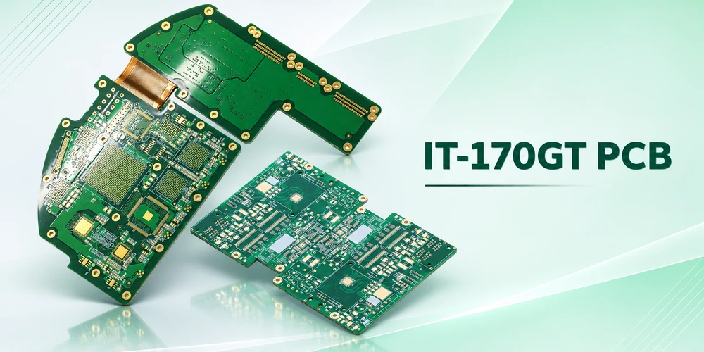
Multilayer PCB illustration. Qualification should represent the actual plated-hole construction.
Diagnose opens that appear only after heat
When an open appears after thermal exposure, first localize the failing net and check when the resistance changes. A continuity test after cooldown can miss an intermittent open. If the application calls for thermal qualification, define a coupon with the relevant hole types, the conditioning and exposure sequence, and when resistance will be measured. Use the applicable IPC-TM-650 methods and purchasing criteria agreed for the build. Typical laminate data do not set board acceptance thresholds.
- Crack through the barrel wall: section the suspect hole at useful orientations and check whether the break passes through plated copper. Review barrel thickness distribution, hole geometry and the thermal history.
- Separation at an inner-layer connection: inspect the specific land-to-barrel interface and look for drilling, smear removal or metallization evidence. Continuous copper on an adjacent barrel wall does not clear the suspect junction.
- Unsound solder joint or poor pin contact: test across the joint or contact separately from the bare-board net. Investigate joint wetting, solder fill or the connector insertion conditions before applying a laminate change as a corrective action.
Preserve the failed unit and compare it with an unstressed specimen when practical. A section through a healthy plane of the same hole can miss a localized crack. Resistance monitoring, physical sectioning and inspection of the assembly answer different parts of the diagnosis.
ΚΑΤΑΣΚΕΥΗ & ΣΥΝΑΡΜΟΛΟΓΗΣΗ PCB
Planning an IT-170GT PCB build?
Η Highleap μπορεί να εξετάσει μαζί τις απαιτήσεις κατασκευής και συναρμολόγησης της πλακέτας.
Include finished hole tolerances, board thickness and the thermal exposures expected at assembly and in use.
Define the first article around the actual heat exposures
Separate the assembly exposure from the service duty cycle. Specify proposed reflow and through-hole soldering steps, planned rework exposures where relevant, and the operating and cycling conditions imposed by the product. Profile areas with different thermal masses on the populated build. A soldered connector near a large plane can heat more slowly than nearby small SMT parts, so a process adjustment must be checked at both locations.
Highleap Electronics reviews these requirements as part of the combined PCB fabrication and assembly scope. Include the controlled stack-up, drill and finished-hole requirements, connector drawings, qualification coupon, BOM and exposure plan in the manufacturing inquiry. The first-article plan can then identify which holes to section, when to monitor resistance and which connector checks belong after assembly.

Σχετικά με το Συγγραφέας
Σαμπρίνα
Ειδικός Μηχανικής PCB στην Highleap Electronics
Η Sabrina έχει πάνω από 18 χρόνια εμπειρίας στον κλάδο των PCB, με ισχυρό υπόβαθρο στη μηχανική CAM και στην αναθεώρηση αρχείων PCB. Υποστηρίζει έργα PCB από το πρωτότυπο έως την μαζική παραγωγή, εστιάζοντας στην κατασκευασιμότητα και την αξιοπιστία της διαδικασίας.
Η εργασία της βοηθά τις ομάδες μηχανικών να μειώσουν τον κίνδυνο παραγωγής και να επιτύχουν σταθερά, υψηλής ποιότητας αποτελέσματα κατασκευής PCB.

συνιστάται Δημοσιεύσεις
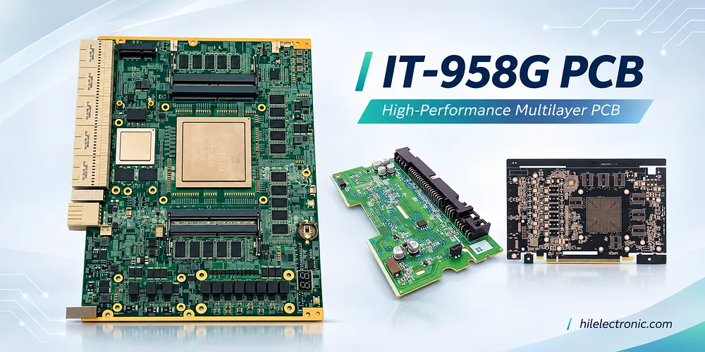
Πλακέτα IT-958G για διακομιστές υψηλής ταχύτητας και backplanes
IT-958G multilayer PCB examples for server and high-speed...
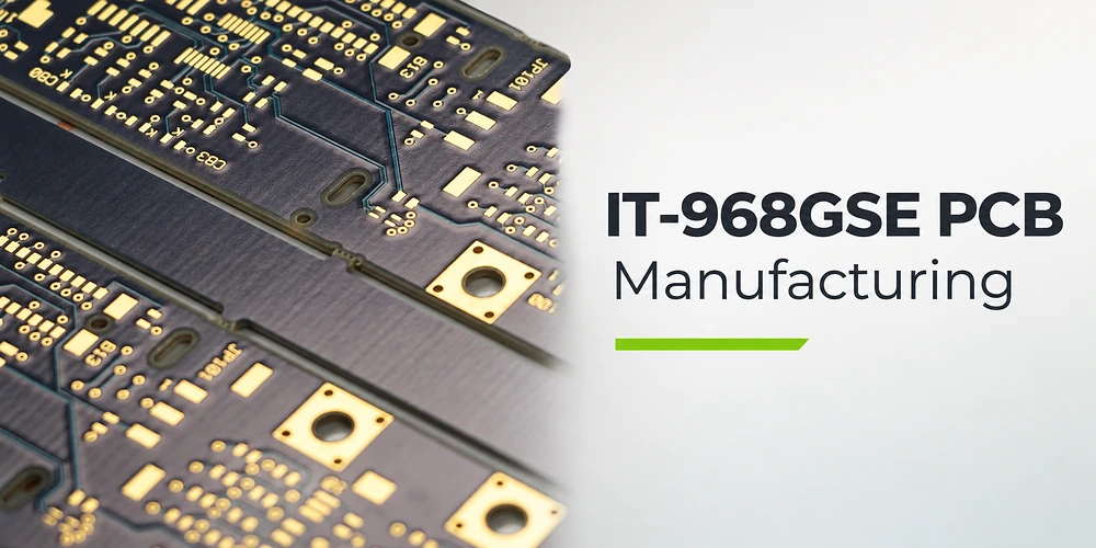
IT-968GSE πλακέτα τυπωμένου κυκλώματος για δικτύωση υψηλής ταχύτητας
IT-968GSE απεικόνιση πλακέτας τυπωμένου κυκλώματος για διακόπτη εξαιρετικά χαμηλών απωλειών και...
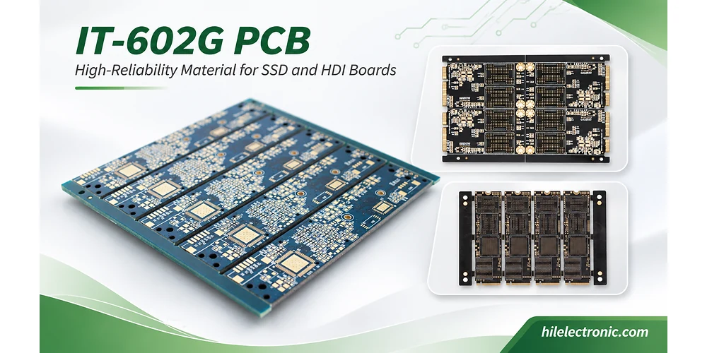
Κατασκευή πλακετών HDI IT-602G για SSD και μονάδες μνήμης
Παραδείγματα πλακέτας IT-602G για HDI, SSD και μονάδες μνήμης...
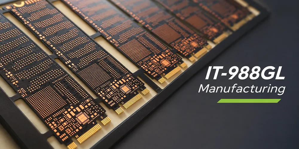
Πλακέτες βασικού πλακέτας IT-988GL με έλεγχο διεργασίας χαμηλού CTE
Κατασκευή πολυστρωματικών PCB IT-988GL...
Πώς να λάβετε προσφορά για πλακέτες τυπωμένων κυκλωμάτων (PCB)
Ας εκτελέσουμε ανάλυση DFM/DFA για εσάς και ας επικοινωνήσουμε μαζί σας με μια αναφορά. Μπορείτε να ανεβάσετε τα αρχεία σας με ασφάλεια μέσω του ιστότοπού μας. Χρειαζόμαστε τις ακόλουθες πληροφορίες για να σας δώσουμε μια προσφορά:
-
- Gerber, ODB++ ή .pcb, spec.
- Λίστα BOM εάν χρειάζεστε συναρμολόγηση
- Ποσοτητα
- Χρόνος στροφής
Εκτός από την κατασκευή PCB, προσφέρουμε μια ολοκληρωμένη γκάμα ηλεκτρονικών υπηρεσιών, όπως σχεδιασμό PCB, PCBA και ολοκληρωμένες λύσεις. Είτε χρειάζεστε βοήθεια με την πρωτοτυποποίηση, την επαλήθευση σχεδιασμού, την προμήθεια εξαρτημάτων είτε τη μαζική παραγωγή, παρέχουμε ολοκληρωμένη υποστήριξη για να διασφαλίσουμε την επιτυχία του έργου σας.
Για υπηρεσίες PCBA, παρακαλούμε να μας δώσετε τον Πίνακα Υλικών (BOM) και τυχόν συγκεκριμένες οδηγίες συναρμολόγησης. Προσφέρουμε επίσης ανάλυση DFM/DFA για τη βελτιστοποίηση των σχεδίων σας για κατασκευασιμότητα και συναρμολόγηση, διασφαλίζοντας μια ομαλή διαδικασία παραγωγής.