
RIGID + FLEXIBLE ZONES · HIGHLEAP
14-lags Rigid-Flex PCB-producent i Kina til brugerdefinerede OEM-bygninger
Highleap Electronics supplies custom 14 layer rigid-flex PCB fabrication in China for integrated rigid and flexible electronic assemblies. Our public PCB capability portfolio includes rigid-flex manufacturing beyond fourteen layers, with polyimide flexible circuits, rigid multilayer sections, coverlay, specialist lamination and coordinated PCBA services. The approved construction is established from the actual rigid-area layer count, flexible copper layers, bend geometry, via connections and assembly conditions—not simply from the label “14-layer rigid-flex.”
A fourteen-layer rigid-flex design does not necessarily have fourteen copper layers in the bend area. For many products the rigid regions carry the full interconnect count, while only selected inner flex layers continue through the hinge. Highleap can review this construction against the specified materials and fabrication sequence. Its PCB fabrication capability comparison lists separate process envelopes for rigid, flexible and rigid-flex PCB families, and their individual maxima should not be treated as interchangeable.
Send the rigid and flex stackups, bend requirements, mechanical drawing and target quantity.
14-Layer Rigid-Flex Stackup and Materials
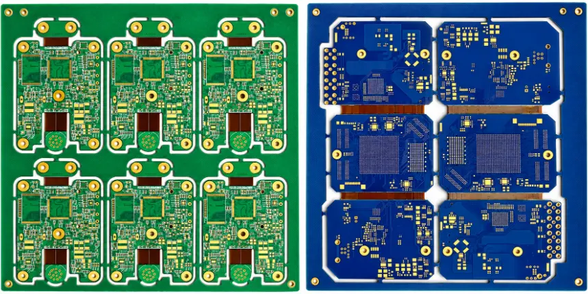
Highleap reviews released rigid-flex stackup drawings, flexible copper artwork, bend and fold geometry, coverlay windows, component keep-outs and plated-hole structures before quoting. A successful manufacturing proposal specifies not only how the rigid sections are pressed, but also how the flex is kept free of unwanted resin, where copper transitions enter rigid areas and how the finished assembly will be handled without bending stress near solder joints.
The manufacturer’s responsibilities can include material procurement, flex circuit formation, rigid-flex lamination, routing/profile finishing, electrical testing and contract-defined quality records. Component population, stiffener installation, programming and box-level integration can be incorporated when separately agreed. Highleap’s rigid-flex manufacturing process describes the general production stages; the actual sequence follows the approved product-specific cross-section.
Can Highleap quote a fourteen-layer board with only two or four flexible layers?
Yes, this is an appropriate construction to assess. Specify which copper layers extend through the bending zone, whether the flex circuits are two- or four-layer and where they enter the rigid boards. The finished rigid-area stack and flex-area thickness are different drawing requirements. A quote should confirm the number of functional flex conductors, bend radius, coverlay and layer-to-layer interconnection strategy before treating the design as feasible.
When the mechanical architecture can accommodate separate boards and connectors, the standard fourteen-layer rigid PCB manufacturing route may be simpler to source and rework. Where the design requires integrated folded interconnects, the rigid-flex zone drawing—not a generic rigid-board stackup—determines the actual fabrication requirements.
Rigid-Flex Layer Stackup, Flexible Zones and Rigid Transitions
A buildable cross-section needs separate material and thickness specifications for rigid zones, flex zones and rigid-to-flex transition zones. Rigid-area prepregs, cores and surface finish may be incompatible with the desired bend construction if they are allowed to flow into the hinge. No-flow prepregs, coverlay boundaries, adhesive windows and controlled routing help preserve the flexible region; each has its own fabrication tolerance.
| Board zone | Typisk konstruktion | Acceptance emphasis |
|---|---|---|
| Stiv sektion | Specified rigid copper layers, cores and prepregs. | Thickness, drilling, impedance and component land geometry. |
| Fleksibel sektion | Selected PI copper layers with coverlay and flex-specific thickness. | Copper strain, coverlay openings and bend profile. |
| Rigid-to-flex transition | Controlled adhesive/flow boundaries and conductor support. | Microcracks, delamination, radius and strain concentration. |
For a fourteen-layer rigid section, the flex copper can be positioned near the mechanical neutral axis as appropriate to the bend requirements. Not all fourteen layers should be routed through the hinge merely because they exist in the rigid portion. The stackup drawing must identify copper continuity, exposed flex windows, any rigid layers terminating before the bend, and the order in which the materials are bonded. A drawing that shows only the rigid laminate thickness is not sufficient to release a rigid-flex PCB.
How is a 14-layer rigid-flex PCB different from a 14-layer flex PCB?
The terms are not interchangeable. A fourteen-layer flexible PCB has a different complete layer construction and flex capability envelope, while a fourteen-layer rigid-flex PCB can have fourteen layers in rigid regions with fewer flexible conductors in the transition. The quotation should always state the layer count by zone, rather than leaving the number of flex layers ambiguous. For high-density flex sections, our HDI flex PCB manufacturing information provides additional process context.
Polyimide, Adhesiveless Flex Cores and Lamination Materials
Highleap’s rigid-flex projects can be evaluated using polyimide flex cores, suitable copper foils, rigid FR-4 materials, prepregs, no-flow bonding materials, coverlay and optional stiffeners. Adhesiveless PI constructions can help reduce flex thickness, but their suitability depends on electrical, thermal and peel-strength requirements. Rolled-annealed copper is often selected for regions subject to repeated flexing; the decision still requires the specific bend and conductor construction to be approved.
For the rigid area, an advanced high-Tg or lower-loss dielectric may be considered where temperature or high-speed routing needs it, subject to bonding compatibility with the selected flex materials. Exact material brands should not be presented as stocked or interchangeable merely because they share a similar Dk. The OEM must approve both the rigid laminate and flex stack materials as one integrated system.
Can a fourteen-layer rigid-flex PCB use a specified PI grade or a custom stiffener?
A material-controlled quotation can include the polyimide grade, copper type, adhesive/adhesiveless construction and the requested FR-4, PI or metal stiffeners. The fabrication drawing must define stiffener location, local thickness, attachment method and any keep-out around solder pads or bends. Material supply and compatibility are confirmed during engineering review rather than assumed from a generic list of available materials.
Bend Radius, Flex Zones and Mechanical Reliability
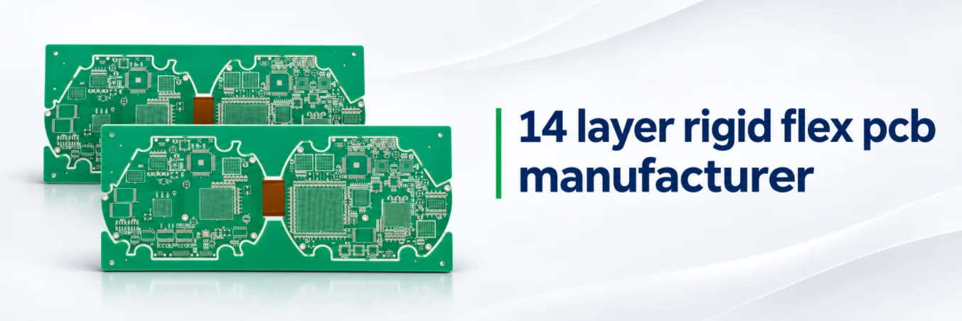
Bend radius depends on flex thickness, layer count, copper construction and whether bending is static or repeated. An arbitrary multiple of total rigid board thickness is not a usable design rule. The flex-only thickness and the mechanical path of the finished assembly matter, as do nearby coverlay openings, stiffeners, plated holes and the boundary between rigid and flex regions.
Keep solder joints, high-stress transitions and plated through-holes out of active bending zones unless a specifically qualified design requires them. A folded module must also account for thickness buildup, component height, mechanical retention and the final installed angle. The customer should provide a folded 3D model or assembly drawing as well as a flat PCB outline.
Can the same 14-layer rigid-flex construction support dynamic flexing?
Not automatically. A static bend, made once during installation, is different from thousands of service cycles. Dynamic bending requires a construction evaluated for the intended radius, cycle count, copper foil, conductor direction and environment. Highleap can review the stated mission profile, but lifetime cycle performance is not a default consequence of selecting polyimide; it needs a suitable design and a defined qualification test.
What manufacturing data define the finished flexible section?
The flat drawing should separately dimension the exposed flex length, rigid island boundary, coverlay overlap, copper traces entering the bend and any adhesive or stiffener edge. A second drawing or 3D model should show the installed fold configuration, minimum bend radius, fixing points and the location of components near rigid-to-flex transitions. The fabrication and assembly teams also need to know whether folding is a one-time installation operation or a repeated motion during service.
Copper foil rolling direction where relevant, the intended static or dynamic bend profile, the local stack thickness and nearby plated holes all change the mechanical design. If a flexible section must survive a defined number of cycles, request a customer-approved bend-fatigue qualification plan and representative samples. Neither the count of rigid-area layers nor the presence of polyimide is a substitute for those checks.
HDI Features, Applications and PCB Assembly
High-density processors and compact optical, medical or industrial modules may require laser microvias and fine BGA escape in their rigid sections. The selected microvia span and sequential lamination procedure must remain compatible with the internal flex layers and rigid-to-flex transition. Fine-pitch pad support, via fill and solder mask require separate DFA review before committing the assembly design.
If a design calls for stacked microvias close to a hinge, pay special attention to local strain and cross-section inspection. The rigid-section HDI approach should not be transferred unchanged into the flex bend area. The adjacent HDI PCB manufacturing guidance helps evaluate the high-density rigid component zone, but the rigid-flex material and mechanical drawing remain the controlling specification.
14 Layer Rigid-Flex PCB Manufacturing for Compact Electronic Modules
Highleap can assess fourteen-layer rigid-flex boards for multi-board camera assemblies, compact instrumentation, medical equipment modules, optical communication hardware, robotics controllers, embedded computing products and other mechanically constrained electronics. In these projects the integrated flex transition can remove a board-to-board connector or cable, but it also makes the PCB part of the mechanical architecture and assembly sequence.
For a camera module with multiple small rigid islands, component locations and fold direction control the final mechanical fit. An industrial vision controller may instead prioritize impedance, EMI grounding and connector mounting in larger rigid portions. Medical-device or aerospace product certification is not implied by the PCB construction; qualification requirements and nominated manufacturing site should be established for the program.
What makes a rigid-flex project a good candidate for one-stop assembly?
A build that replaces several separately purchased boards and cable interconnects can benefit from a coordinated fabrication, component and final folding plan. The commercial scope should specify when the board is populated, whether the flex is formed before or after functional test, and which fixtures prevent mechanical damage. If electrical testing occurs only in the flat state, the final folded configuration may still require an additional acceptance step.
Assembly, Stiffeners, Programming and Final Folded Delivery
The PCBA quotation should identify SMT placement on rigid islands, any connectors or through-hole hardware, adhesive or stiffener operations, programming, required electrical tests and final folding or installation tasks. Solder paste printing and reflow fixtures must support the rigid areas without placing excessive stress on exposed flex segments. Rework, cleaning and ESD packaging need their own handling restrictions.
Highleap can coordinate these activities through its PCB assembly and box-build services. If the customer requires final installed-shape testing or integration into a housing, the fixture, required mechanical restraint, pass/fail limits and ownership of supplied parts should be quoted explicitly rather than assumed under “assembly included.”
Rigid-Flex Quality Control and First-Article Testing

Rigid-flex quality is not fully described by a rigid PCB electrical test. Inspection can include inner-layer AOI, coverlay position and adhesion, lamination interfaces, plated interconnects, outline accuracy, surface-finish condition, flex-window damage and continuity/isolation. Where the assembly requires repeated bending, a specific bend/fatigue qualification plan and mechanical acceptance limits must be separately defined.
Brug den gældende IPC-6013 performance requirements and customer-specific acceptance details for flexible and rigid-flex circuits. A fabrication inspection report should identify the construction revision, inspected features, sampling and any concessions. A rigid-board IPC-6012 callout alone is not a substitute for defining flex-region workmanship and reliability. For general material and processing controls, the flexible PCB manufacturing resource is a related reference.
Which tests belong in a rigid-flex first article?
In addition to the specified netlist continuity/isolation test, a first article may need dimensional inspection in the flat condition, critical transition-zone cross-sections, coverlay and stiffener checks, and functional or mechanical testing in the folded configuration. Destructive peel or bend tests are usually sampled rather than applied to every sellable unit. The actual evidence should be listed before fabrication and accepted by the customer’s design authority.
Prototype Cost, Lead Time and Production Transfer
Rigid-flex pricing is affected by flex core and coverlay materials, the rigid-section stack, lamination/cavity tooling, flex outline, transition geometry, plated interconnects and the ordered inspection plan. A small prototype with unusual stiffeners or complex profiling can carry significant setup cost. The schedule is tied to the approved material route and tooling and should not be assumed from a standard rigid 14-layer PCB lead-time advertisement.
Highleap can plan the first engineering lot as a manufacturing baseline for later repeat production. The relevant PCB prototype and DFM review should record the rigid/flex layer counts, flat and folded dimensions, accepted bend scheme and any assembly restrictions. If the project includes an enclosure or a packaged sensor module, a turnkey assembly handoff should also record firmware or fixture ownership rather than leaving the final-fold acceptance unresolved.
Should a rigid-flex quote include a tooling and test breakdown?
Yes. Ask for clarity on bare-board fabrication, any one-time tooling, special stiffeners, optional bend qualification, component population, final folding, electrical/functional checks and packaging. A conventional 14-layer rigid-board quotation is not directly comparable to a 14-layer rigid-flex populated module with formed flex zones. For general PCB cost drivers, see the manufacturing quotation methodology and provide the exact rigid-flex drawing for an actual price.
Request a 14-Layer Rigid-Flex PCB Quote
Send flat Gerber/ODB++ data, rigid and flex zone cross-sections, individual material thicknesses, coverlay/stiffener drawings, drilled and blind via maps, bend radius and cycle requirement, mechanical flat/folded dimensions, surface finish, test standard, quantities and required delivery. For populated builds include the approved BOM, placement drawing, assembly sequence and final-state test requirements.
Highleap can prepare a fabricator review that identifies the permitted material and layer architecture, special tooling, inspection expectations and the manufacturing/assembly responsibilities before production release.

anbefalet Indlæg

AlN Keramisk PCB-producent til højtermisk ydende elektronik
HIGHLEAP ELECTRONICS · Aluminiumnitrid Keramisk PCB...

Fremstilling af aluminiumoxid-printkort til OEM-prototyper og -produktion
HIGHLEAP ELECTRONICS · Fremstilling af aluminiumoxidkeramiske printkort...

Leverandør af printkortmontering til OEM- og ODM-elektronikproduktion
HIGHLEAP ELECTRONICS · OEM / ODM PCB-monteringsleverandørDin...
Al2O3 keramisk printkortproducent til præcisionskeramiske kredsløb
HIGHLEAP ELECTRONICS · Aluminiumoxid keramisk kredsløb...
Sådan får du et tilbud på printkort
Lad os køre en DFM/DFA-analyse for dig og vende tilbage til dig med en rapport. Du kan uploade dine filer sikkert via vores hjemmeside. Vi har brug for følgende oplysninger for at kunne give dig et tilbud:
-
- Gerber, ODB++ eller .pcb, spec.
- Stykliste, hvis du ønsker montering
- Antal
- Vendetid
Udover printkortproduktion tilbyder vi en omfattende vifte af elektroniske tjenester, herunder printkortdesign, printkortbaseret udstyrs ...
For PCBA-tjenester bedes du fremvise din BOM (Bill of Materials) og eventuelle specifikke monteringsinstruktioner. Vi tilbyder også DFM/DFA-analyse for at optimere dine designs med hensyn til fremstillingsevne og montering, hvilket sikrer en problemfri produktionsproces.