
PLC-printplaatassemblage voor CPU-, I/O- en communicatiemodules
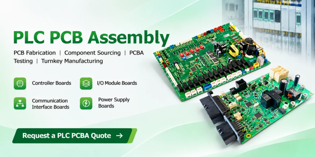
A PLC may contain a single main PCBA, stacked circuit boards or multiple replaceable modules. The required manufacturing process depends on the actual hardware architecture. Highleap manufactures to the approved OEM design package, including the agreed components, mechanical interfaces and acceptance requirements. Compatibility with an existing PLC platform, product certification and system-level testing must be specified and verified as part of the project scope.
Need assembled PLC boards or a complete multi-board set?
Send PCB data, module BOMs, quantities per controller and any required programming or functional-test specifications.
PLC PCB Assembly for Compact, Modular and Rack-Based Controllers
Compact and modular PLCs do not require the same PCB assembly plan. A compact controller may integrate its CPU, power conversion and fixed I/O on one populated board or a small board stack. A modular controller can use separate CPU, power and I/O modules connected through an inter-module bus. Rack-based systems may use a dedicated backplane PCB, while others distribute bus connections through individual module connectors. The number of PCBAs is determined by the OEM’s product design, not by the PLC category alone.
| Hardware configuratie | Typical assembly scope | Manufacturing / test emphasis |
|---|---|---|
| Compact or micro PLC | Integrated main PCBA or compact mainboard plus daughterboard | Terminal alignment, enclosure clearance, power and fixed-I/O testing |
| Modulaire PLC | CPU, digital/analog I/O, communication and optional power modules | Inter-module connector fit, board revision compatibility, slot/channel identification |
| Rack-based PLC / PAC | Plug-in modules with a backplane PCB or other manufacturer-defined bus interconnect | Connector geometry, rack alignment, power distribution and bus checks |
| Distributed I/O node | Remote I/O electronics with network interface and field terminals | Field-channel operation, network identity and remote-power requirements |
Distributed I/O is often a peripheral subsystem of a PLC installation rather than a separate PLC CPU. Similarly, motion-control, redundant and safety-related functions can be incorporated into several of the hardware configurations above. Their manufacturing requirements follow the approved hardware design and acceptance criteria; a safety-rated system requires separate product-level functional-safety assessment.
Can one PLC require several different PCB assemblies?
Yes. A modular controller can require individual CPU, power, input/output and communication PCBAs; some products also include a backplane or interconnect board. Each assembly needs its own part number, revision, component list and inspection criteria. The completed controller may additionally require integration checks that cannot be performed on the boards individually.
Highleap's PLC PCB manufacturing capabilities cover the bare-board construction used in industrial control equipment. For an assembled PLC, the manufacturing release must additionally define component population, module connection and electrical acceptance.
PLC CPU, Power Supply, I/O, Communication and Backplane PCB Assembly
Multi-board PLC production should start with a board-set configuration: every PCBA part number, hardware revision, quantity per controller and required test. It is possible to manufacture every board in an order correctly yet deliver an unusable system because a module is missing or incompatible with the intended CPU/backplane revision.
PLC CPU / Main Control PCBA
MCU/MPU, flash, clocks and board-level power. Review fine-pitch soldering, boot access, firmware version and controller-to-bus connections.
Voeding PCBA
Input protection, DC/DC conversion and distribution. Review polarity, thermal components, output regulation and test loads.
Digital I/O Module PCBA
Input conditioning and relay/transistor output stages. Check field connector fit, channel address, electrical thresholds and output operation.
Analog / Temperature I/O PCBA
4–20mA, voltage, RTD or thermocouple channels as designed. Plan accuracy checks, reference handling and any required calibration.
Communication Module PCBA
RS-485, CAN, Industrial Ethernet or other specified links. Confirm interface parts, termination options, module identity and protocol checks.
Backplane / Interconnect PCBA
If the design uses one, verify board connectors, slot assignment, power/ground distribution, mechanical fit and specified bus signals.
Other customer designs may contain high-speed counter boards, encoder interfaces, isolated field power boards, redundancy interfaces or safety-related modules. These are project-specific assemblies, not mandatory parts of every PLC system. PCB material, plated-hole construction, controlled impedance or connector footprint requirements should be established in the custom PLC circuit board design and fabrication package.
Example: multi-board PLC assembly set
1 CPU board + 1 power board + 2 digital I/O boards + 1 analog I/O board + 1 communication board + 1 backplane board = 7 assembled PCBs per controller.
For a production order, the board-set BOM must specify the actual quantities and hardware revisions. PLCs using inter-module bus connectors may not have a separate backplane PCB.
How should a factory quote a PLC containing several PCBAs?
The quote should list each distinct PCBA and the quantity needed per finished controller, then identify any additional programming, test fixtures, module assembly, inter-board checks and packing. Individual spare modules and full controller sets can have different unit costs because their acceptance and integration scopes differ.
Have separate BOMs for your PLC modules?
Request one quotation covering individual PCBAs and the complete configured board set.
24V PLC Control Board Manufacturing: DFM and Mixed SMT/Through-Hole Assembly
PLC assembly design-for-manufacturing must address electrical and mechanical interfaces together. Many industrial controllers use 24VDC control power, although supply voltages, field I/O ratings and isolation requirements vary by design. An assembler must work from the specified maximum conditions and actual drawings, not treat “24V PLC” as a complete electrical specification.
Typical industrial controller assemblies combine compact SMT components with terminal blocks, relays, transformers, bus connectors and larger power devices. During the ontwerp-voor-productie beoordeling, check component footprints, connector coplanarity, through-hole fit, soldering access, thermal mass, isolation boundaries and test-pad accessibility. On multi-board units, pay particular attention to mating height, card guides, slot connectors and enclosure clearances. Finished hole sizes, copper construction and panel requirements should also be aligned with the PCB-fabricagepakket before assembly tooling is released.
| Montagefunctie | Productierisico | Vereiste technische input |
|---|---|---|
| Field terminals / relays | Poor solder fill, tilted connectors, wrong variant or inadequate mechanical support | Approved MPN, mounting drawing, mating requirements and inspection criteria |
| CPU / communication ICs | Fine-pitch solder defects, package mismatches, inaccessible programming contacts | Exact component/package, test access and programming procedure |
| Machtsverdeling | Thermal stress, polarity errors, high-current joint problems or insufficient fixture load capacity | Input/output ratings, thermal limitations and test conditions |
| Inter-board bus / connector | Misalignment, damaged contacts, incorrect slot assignment and board flex | Connector drawings, tolerances, slot map and assembly sequence |
| Isolated field interface | Incorrect component variant or conflict with designed clearance/creepage | Approved isolation boundary, operating voltage and applicable requirements |
Highleap's SMT- en doorsteekmontage van printplaten can be scoped to mixed-technology industrial controller designs. SMT reflow, insertion soldering, inspection and any protective finishing should be sequenced around the actual component limitations and required test access. For fine-pitch or hidden-joint devices, the agreed inspection plan may call for X-ray; for large through-hole connectors, solder fill and mechanical alignment may be more significant.
Does a modular PLC always need a special backplane PCB?
No. Some designs use a separate passive or active backplane PCB; others connect modules using bus connectors or other interconnect structures without a full-length backplane board. Highleap manufactures the PCBAs defined in the OEM’s released design and can review the mating and assembly requirements for the specified connection method.
PLC I/O Module Testing and Multi-Board System Verification
A tested PLC PCBA is not automatically a tested PLC system. Bare-board electrical testing checks continuity and isolation; AOI and X-ray examine aspects of soldering workmanship. Module functional tests verify specified on-board functions. The assembled controller additionally needs the agreed checks for bus communication, power distribution, channel mapping and module compatibility.
| Module / function | Board-level functional check | Complete-set check (when contracted) |
|---|---|---|
| CPU-bord | Power-up, device identity, approved firmware and local interface response | Recognizes intended modules and maps configured slots/channels |
| Power board | Specified output rails, current and behavior under defined load | Modules receive specified power with expected startup behavior |
| Digital input/output cards | Customer-specified input levels and output switching/load points | CPU addresses each installed module and intended field channel |
| Analog / temperature cards | Approved measurement points, tolerance and calibration if specified | Controller displays/receives correctly mapped and scaled data |
| Communication / remote I/O | Defined interface transaction and configured device identity | Specified network exchange and fault response |
| Backplane or inter-module bus | Board/interconnect continuity, connectors and power nets | Slot, power and data-path checks with appropriate modules or simulator |
De goedgekeurde functional test procedure and fixture should define stimulus, load, programmed test mode, measurement limits, sample or unit coverage and required records. For example, 4–20mA inputs may be checked at selected calibrated points and a digital-output card may be exercised under specified representative loads. The values and limits must come from the OEM’s product design, not from a generic PLC category.
Can PLC modules be tested without assembling a complete controller?
Individual modules can often be tested in dedicated fixtures or with known-good reference hardware. A backplane or bus interface may also be checked with test adapters. These methods validate the conditions included in the procedure; they do not by themselves establish system-wide interoperability or commissioning in the customer’s machine.
Does board-level PLC testing prove IEC 61131-2 compliance?
Nee. IEC 61131-2: 2017 covers functional and electromagnetic-compatibility requirements and associated tests for programmable controllers and related equipment. Product safety requirements are addressed separately, including under IEC 61010-2-201: 2024 where applicable. Normal assembly inspection or production FCT is not a substitute for product-level qualification. For a safety-related controller, functional-safety validation and certification are separate from PCB workmanship acceptance.
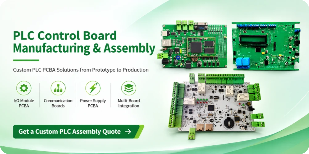
Industrial PLC PCB Assembly for CPU, I/O and Communication Modules
Industrial PLC PCB assembly is best quoted as a defined module family with clear electrical interfaces and acceptance criteria. A CPU board, digital input card, relay output card, analog input module and communication board can have different component mixes, test points and mechanical interfaces. For a modular controller, the OEM should provide a board-set matrix showing each module part number, hardware revision, quantity per controller and permitted configuration.
Digital input and output modules may use optocouplers, isolation devices, transistor drivers, relays, protection components and terminal blocks. Analog modules may include precision references, amplifiers, ADCs, current-loop interfaces and temperature-sensing circuits. Communication modules may use RS-485, CAN, Ethernet or another specified interface. These functions influence component sourcing, soldering access, calibration, test-fixture design and the records needed for acceptance.
Manufacturing and test considerations by PLC module
- CPU and main control: MCU/MPU, memory, clock, programming access, boot verification and revision identification.
- Digital input/output: channel mapping, input thresholds, output type, representative load, protection and terminal-block workmanship.
- Analog input/output: signal range, reference accuracy, calibration points, channel isolation and measurement tolerance.
- Stroomvoorziening: input range, protection, output rails, defined load conditions, thermal components and polarity.
- Communicatie: transceiver variant, termination options, connector pinout, module identity and protocol-level test boundary.
- Backplane or inter-module connection: connector alignment, slot assignment, power distribution and specified bus continuity or communication checks.
For a 4–20mA input module, for example, the OEM should provide the required test points, stimulus method, calibration procedure and acceptance tolerance. For a relay output card, the test package should define the load and switching conditions. A generic statement such as “PLC functional test” does not provide enough information to establish a repeatable test procedure.
PLC module manufacturing from prototype to repeat order
During prototype production, confirm the mechanical fit of terminal blocks and card connectors, the module’s slot or address identification, firmware version and the agreed I/O test method. Record any component or layout changes and update the board-set matrix before pilot or volume production. When several modules ship as one controller kit, label and pack them by the approved configuration so the customer can identify which revisions belong together.
PLC Firmware Programming, Module Identification and Revision Control
PLC programming during PCBA manufacturing means loading and verifying the approved device firmware or configuration needed for the delivered hardware. It is not the same as developing the customer’s PLC application logic or commissioning a plant. Depending on the architecture, CPU modules, network cards and selected I/O boards may have different firmware images, calibration data and hardware revision requirements.
Highleap lists IC programming and firmware loading among its assembly services. Programming can be evaluated through an in-circuit interface such as SWD/JTAG or a device-specific boot connection, or by programming compatible devices before assembly. The selected method must match the target component and approved access design.
Firmware and hardware release record
- Hardware: module part number, PCB/PCBA revision and exact programmable device variant.
- Software: approved image, bootloader or configuration, release/checksum identification and applicable test mode.
- Programmering: interface pinout, voltage, verification steps and authorization for protected-memory settings.
- Identificatie: serial number, network identity, calibration constants or module address when required.
- traceerbaarheid: agreed association of program result, module identity and final system configuration.
Do all PLC circuit boards require firmware programming?
No. A passive backplane or a simple unprogrammed interface board may not need it. CPU boards and some network or intelligent I/O modules can require different firmware or configuration files. Each programmable assembly should be listed separately in the released programming matrix, and write/verify success should not be confused with functional-test acceptance.
Turnkey PLC PCBA Manufacturing and Electromechanical Box Build
Turnkey PLC PCBA production can include PCB fabrication, component procurement, assembly and defined inspection or testing under one manufacturing project. For a multi-board controller, the shipment must contain the correct quantity and revision of each specified module, including any power or bus assemblies that are part of that design. Highleap’s kant-en-klare PCB-assemblageservice offers this coordinated manufacturing scope for approved customer designs.
Critical industrial components—including isolation devices, precision references, connectors and selected controllers—may have sourcing restrictions or long lead times. Through component sourcing and procurement, availability and candidate alternatives can be reviewed before production. An alternative that fits the footprint is not automatically acceptable; changes affecting electrical function, safety-related requirements, calibration or field compatibility require OEM approval.
When the ordered item is a housed PLC controller or completed module, Highleap’s electromechanical box-build integration can be considered for enclosure mounting, cables, module seating, labeling, firmware installation and final checks. The quotation must state whether it covers loose PCBAs, assembled modules or complete units. Product design ownership, safety qualification and installation commissioning remain separate unless specifically agreed.
What changes between an individual PLC module order and a complete controller set?
Individual modules can be quoted and accepted against their own drawings and test procedures. A configured controller set additionally requires a bill of assemblies, allowed hardware/firmware combinations, integration instructions, inter-board test scope and labeling/packing rules. These extra operations should be priced and scheduled explicitly.
PLC PCB Assembly Quotation: Files, Test Requirements and Pricing Scope
A complete PLC PCB assembly RFQ identifies every board and the required delivery state. Pricing depends on board construction, BOM availability, SMT/THT process mix, connector and relay content, programming, test fixtures, module integration, order quantity and any required documentation. The following package supports a useful engineering review:
- Per-board PCB data: Gerber/ODB++, stack-up, drill data, fabrication drawings, finishes and critical electrical or mechanical features.
- Per-board PCBA data: BOM with exact manufacturer part numbers, approved alternates, pick-and-place/CPL, assembly drawings, DNP flags and module-specific hardware notes.
- Board-set configuration: all PCBA part numbers and revisions, quantity of each per controller, backplane/inter-module connection drawings and module positioning.
- Electrical and communication requirements: power input range, rails and loads, field I/O map, interface settings, connector pinouts and isolation requirements.
- Firmware and test package: image files, target devices, approved version matrix, programming procedure, I/O functional-test limits, fixture or reference-unit requirements and record format.
- Commerciële details: prototype and production quantities, full-turnkey versus consigned components, standalone-module or complete-set shipping, packaging, traceability and requested schedule.
Can Highleap assemble a replacement PLC module without producing the entire controller?
A single OEM-controlled PLC module can be evaluated as an independent PCBA order. The inquiry needs complete authorized manufacturing files, component specifications and the required acceptance criteria. A commercial PLC model number or photograph alone is not enough to establish a compatible replacement or authorize the reproduction of proprietary hardware.
Can Highleap supply PLC PCBA assembly without firmware or an integration fixture?
Yes, where an assembly-only scope is agreed. Programming, module-level FCT and integrated controller testing must be included as separate defined operations if required. If fixtures, test software or production images are not ready, the quotation should identify which items remain open rather than imply that complete system verification is included.
Request a PLC PCB Assembly Manufacturing Quote
Highleap Electronics can review your PLC PCB files, BOMs, module configuration and planned assembly/test scope for a project-specific quotation. Send one board or a complete multi-board PLC design.

aanbevolen berichten
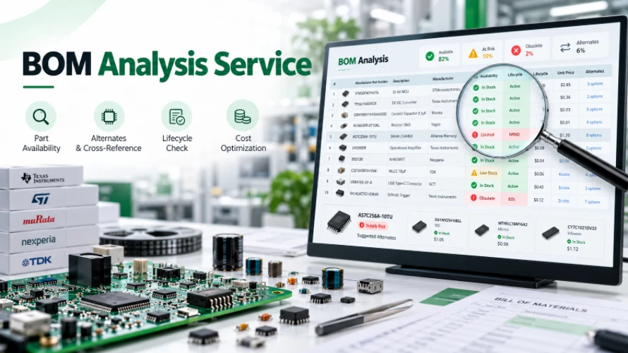
PCB-assemblage met gratis BOM-analyse.
Heeft u een gratis BOM-analyse nodig voordat u een PCB-bestelling plaatst?
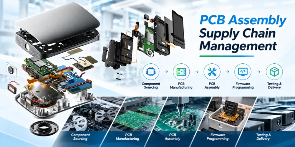
Supply chain management voor PCB-assemblage
Highleap Electronics ondersteunt de toeleveringsketen voor PCB-assemblage...
PCB-assemblage met conformal coating
Highleap Electronics verzorgt de assemblage van printplaten met conforme...
Industriële elektronica PCB-assemblage
De assemblage van printplaten voor industriële elektronica omvat...
Hoe u een offerte voor PCB's kunt krijgen
We voeren een DFM/DFA-analyse voor u uit en sturen u een rapport. U kunt uw bestanden veilig uploaden via onze website. We hebben de volgende informatie nodig om u een offerte te kunnen sturen:
-
- Gerber, ODB++ of .pcb, spec.
- BOM-lijst als u assemblage nodig heeft
- Aantal
- Draaitijd
Naast PCB-productie bieden we een uitgebreid scala aan elektronische diensten, waaronder PCB-ontwerp, PCBA en kant-en-klare oplossingen. Of u nu hulp nodig heeft bij prototyping, ontwerpverificatie, componentsourcing of massaproductie, wij bieden end-to-end ondersteuning om het succes van uw project te garanderen.
Voor PCBA-diensten verzoeken wij u uw BOM (Bill of Materials) en eventuele specifieke assemblage-instructies te verstrekken. Wij bieden ook DFM/DFA-analyses aan om uw ontwerpen te optimaliseren voor maakbaarheid en assemblage, wat een soepel productieproces garandeert.