
Producent elastycznych grzejników PCB do niestandardowych obwodów grzewczych
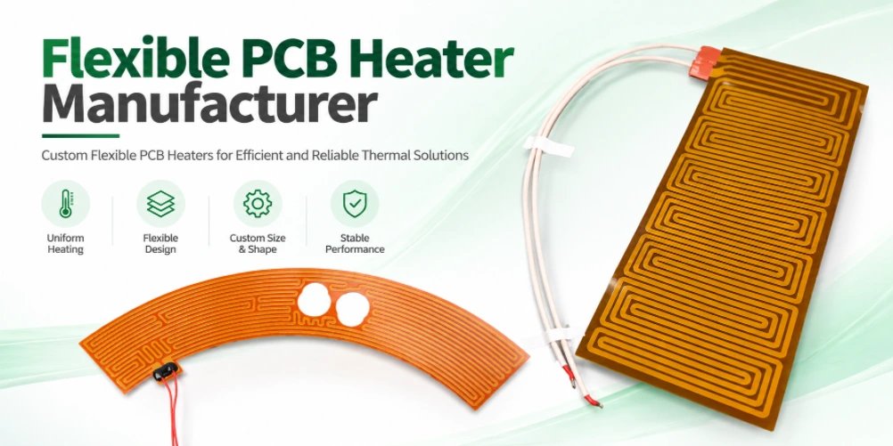
Custom flexible PCB heaters require coordinated electrical, thermal, material and mechanical design. Highleap Electronics can review your heater circuit data and project requirements to clarify the construction and information needed for a manufacturing quotation.
Prześlij dane produkcyjne i kluczowe wymagania do analizy inżynierskiej. Highleap Electronics może ocenić żądaną konstrukcję, wyjaśnić kwestie związane z wykonalnością i przygotować wycenę w oparciu o zatwierdzony zakres.
Flexible PCB Heater Construction and Circuit Layout
A flexible PCB heater uses a conductive pattern on a flexible substrate to generate heat when powered. The design must coordinate heater trace geometry, substrate, coverlay, electrical insulation, thermal spreading, mechanical flexing and mounting interface. Construction depends on temperature range, available area, supply voltage and duty cycle.
Distinguish a flexible printed heater circuit from a complete heating assembly that includes sensors, connectors, insulation or a metal spreader. If the project also needs assembly, discuss the overall scope with usługi montażu płyt PCB Flex i PCB assembly team.
A flexible PCB heater is not simply a standard flex circuit with a serpentine trace. The conductor pattern, substrate, coverlay, connector, mounting method, and thermal interface collectively determine how heat is generated and transferred. The layout must balance electrical resistance with mechanical robustness and the required active heating area. Tight turns, narrow trace necks, and abrupt changes in conductor width can create localized electrical or thermal stress, so the pattern should be reviewed as a functional heating element.
Define the non-heating zones, edge clearances, sensor locations, connector orientation, mounting holes, adhesive areas, and any regions that must remain flexible. If the heater will be bonded to a metal or polymer surface, specify the mating surface and the thermal contact method. A circuit tested in free air may behave differently after installation because heat transfer and thermal mass change the temperature distribution. The design should therefore distinguish bare-circuit requirements from final-assembly performance targets.
Materials, Coverlay and Temperature Requirements
Material selection should consider continuous and peak operating temperature, bend requirements, adhesive or adhesive-less construction, chemical exposure and attachment method. Polyimide is common in flexible circuits, but the exact material stack and temperature limits must match supplier data and the application.
Specify operating environment, thermal cycling, moisture or chemical exposure and cleaning process. The flexible substrate alone does not determine maximum working temperature; copper, adhesives, coverlay, connectors and mounting interface can each be limiting factors.
Material selection should begin with the operating environment rather than a single maximum-temperature number. Consider continuous operating temperature, short-term excursions, thermal cycling, humidity, chemical exposure, cleaning agents, and the mechanical movement expected during service. Polyimide is commonly used for flexible circuits, but the full construction may also include adhesive layers, coverlay, stiffeners, pressure-sensitive adhesive, solder, and connector materials that have different limits.
Specify the required copper type and thickness, dielectric construction, coverlay openings, adhesive system where applicable, and any restrictions on materials. If the heater will be used near liquids, skin contact, food, medical equipment, or other regulated environments, the product-level requirements need separate review; a PCB material choice alone does not establish regulatory compliance. For a design that needs repeated flexing, the material and copper construction should be selected with the bend location and cycle count in mind.
Heater Resistance, Power and Temperature Uniformity
Electrical power relates to voltage and resistance, but resulting temperature also depends on heat loss, substrate contact, airflow, thermal mass and surrounding materials. Review the heater pattern for current density, local hot spots, trace spacing, connector loading and expected resistance tolerance.
Provide target voltage, nominal resistance or power, allowed resistance variation, active heating area, target temperature, warm-up time and control method. If uniform heating matters, state the measurement method and allowable temperature variation.
1. Convert the heating requirement into an electrical specification
Start with the system requirements rather than drawing a serpentine trace immediately. Define the supply voltage, desired nominal power or resistance, active heating area, target temperature, warm-up time, ambient conditions and how the heater will be controlled. For a resistive element, the basic relationships are power equals voltage squared divided by resistance, and power equals current squared multiplied by resistance. These relationships help set an initial electrical target, but they do not predict final surface temperature without a thermal model or representative test.
State whether the resistance is a room-temperature nominal value, a value at operating temperature, or a value measured under a specified test condition. Copper resistance changes with temperature, and the assembled system may have contact resistance at connectors or terminals. If the heater is driven by a constant-voltage supply, resistance variation changes current and power; if it is driven by a controlled current or closed-loop controller, the behavior differs. The control architecture must therefore be part of the design discussion.
2. Design the trace pattern for power distribution
The trace pattern determines how electrical power is distributed over the active area. Trace width, spacing, length, copper thickness, bends, terminal geometry and local heat loss all influence resistance and temperature distribution. A narrow trace or crowded turn can produce a local hot spot, while a broad low-resistance path may deliver less heat than intended in a region. The pattern should be evaluated as a whole, including the feed paths and transition from connector pads to the active heater.
Do not judge uniformity from the visual regularity of the serpentine pattern alone. Edge losses, mounting contact, nearby metal, airflow and insulation can make the same electrical pattern behave differently in different assemblies. Provide the actual mounting arrangement and surrounding materials, and identify zones that must remain cooler or reach a particular temperature. If multiple heating zones are required, show their electrical separation and control strategy.
3. Define temperature uniformity and test conditions
“Uniform heating” is not a complete acceptance criterion. Specify the measurement area, sensor type or measurement method, ambient temperature, applied voltage or power, stabilization time, mounting pressure, thermal interface and allowable temperature variation. If the requirement is a maximum temperature at a defined point, identify that point and the worst-case operating condition. A test performed on an unsupported flex circuit may not represent performance after it is bonded to a housing or spreader.
Thermal validation should consider both steady-state and transient behavior when these matter to the product. Warm-up time, overshoot, cool-down, repeated on/off cycling and response to loss of thermal contact may all be relevant. If a sensor or thermostat is included, clarify whether it is part of the flexible PCB, a separate component, or supplied by the customer. The heater PCB manufacturer can fabricate the circuit to the agreed specification, but system-level temperature performance must be validated in the intended assembly.
4. Consider electrical protection and abnormal conditions
Document the normal operating voltage and current, maximum permitted input, expected duty cycle and any abnormal conditions that the finished product must tolerate. Depending on the application, the complete system may need current limiting, over-temperature protection, a temperature sensor, a fuse or a controller response to sensor failure. These functions should not be assumed to be provided by the copper pattern itself.
Identify the required insulation, creepage or clearance constraints where applicable, as well as the environmental exposure and mechanical protection. If the heater is used near a battery, skin-contact surface, fluid, or combustible material, the product-level risk analysis and applicable safety requirements need to be addressed by the responsible system designer. State the test evidence and documentation required from the PCB supplier, and separate it from any certification required for the complete product.
5. Resistance tolerance, material variation and production control
Set a nominal resistance and an acceptable tolerance that accounts for trace geometry, copper thickness, etching variation, material effects and measurement conditions. If resistance is the primary acceptance parameter, define the measurement temperature, test current or method, connector contact points and whether the measurement is performed before or after adding the connector or other assembly parts. A tolerance that is too narrow for the chosen construction may increase cost or require a different pattern or process review.
For a production quotation, include the required electrical test and lot records. If temperature uniformity is critical, identify whether the supplier is expected to perform a thermal test on every unit, on samples, or only during qualification. These are very different inspection scopes. The most effective brief links the circuit geometry, electrical target, mounting conditions and validation method into one specification so the manufacturer can identify missing information before production.
Electrical design starts with the required supply voltage and target resistance or power. For a resistive element, power depends on voltage and resistance, but the temperature achieved in use also depends on the surface being heated, thermal contact, insulation, airflow, ambient conditions, and control behavior. The same electrical design can produce different temperatures when installed on different substrates or operated under different boundary conditions.
To assess uniformity, define the active heating area, target temperature range, measurement points, stabilization time, and allowed variation. Include any sensor position, control loop, and over-temperature response that the system requires. The trace pattern should be checked for current concentration at corners and transitions, connector heating, and areas where adjacent traces may create a temperature gradient. A thermal test plan should state the mounting method and operating conditions so the result is reproducible.
Bend Radius, Mounting and Mechanical Reliability
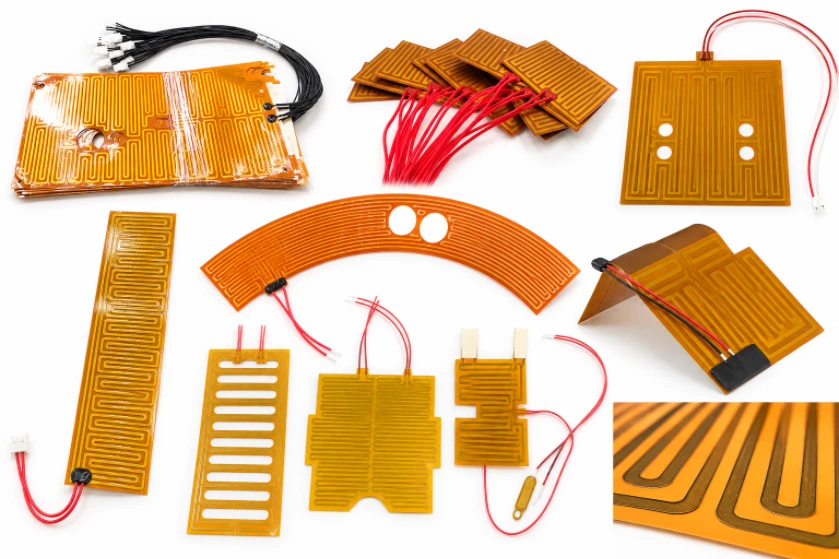
A flexible heater may be static-flex or dynamic-flex. Repeated bending can fatigue copper and stress transitions, while mounting pressure and thermal expansion can affect performance. Define minimum bend radius, bend direction, expected cycle count and keep-out zones.
Provide mechanical outline, mounting holes or adhesive zones, connector position and stiffener details. For combined flexible and rigid regions, review whether a produkcja niestandardowych płytek PCB route or rigid-flex construction is appropriate.
Static-flex and dynamic-flex applications should be specified differently. A static-flex heater may be formed once during installation, while a dynamic-flex heater experiences repeated movement. Repeated bending can strain copper and create fatigue, particularly near stiffener edges, connectors, solder joints, or abrupt changes in construction. The drawing should show the bend line, bend direction, minimum radius, and any zones where components, vias, or stiffeners are not permitted.
Mounting also affects reliability and temperature behavior. Adhesive thickness, clamping pressure, surface flatness, and thermal expansion can change both heat transfer and mechanical stress. If the heater is bonded to a curved part, provide the radius and expected forming method. If it is attached using screws or clips, identify the load points and clearance requirements. These details allow the supplier to review the flexible circuit as part of its real mechanical environment rather than as a flat outline only.
Electrical, Thermal and Safety Validation
Acceptance criteria should address continuity, insulation requirements, resistance, temperature behavior and operating conditions. Depending on the product, validation may include temperature mapping, thermal cycling, dielectric testing or functional testing in the final assembly.
Define who is responsible for heater control, over-temperature protection, sensor integration and system-level safety evaluation. PCB fabrication alone does not certify the completed heating product to a particular regulatory standard.
Validation should separate the electrical checks on the flexible circuit from the thermal and safety evaluation of the finished product. Bare-circuit checks may include continuity, resistance, insulation, and visual inspection. Thermal validation may require temperature mapping at defined voltage, mounting, ambient, and stabilization conditions. Depending on the application, further checks may include thermal cycling, flex cycling, moisture exposure, or testing after mechanical installation.
Define the required records before production: resistance limits, insulation test conditions, thermal map locations, sample quantities, pass/fail criteria, and traceability expectations. System-level protection such as a thermostat, temperature sensor, fuse, or electronic cutoff must be assigned clearly to the product design. PCB fabrication alone cannot guarantee safe operating temperature under every possible fault or installation condition, so the system owner must define and validate the complete protection strategy.
What a Flexible PCB Heater Manufacturer Needs to Quote
Send the outline drawing, Gerber or ODB++ files, stack-up and material requirements, copper thickness, heater resistance or power target, operating voltage, target temperature, active area, coverlay, connector details, bend conditions, quantity and delivery target.
If the design is still developing, provide electrical and thermal targets and identify which values are fixed. Request a quote through the Prośba o wycenę PCB. If component sourcing or assembly is required, review Montaż PCB pod klucz oraz Usługi montażu PCB.
A useful RFQ includes the circuit outline, fabrication data, stack-up, copper thickness, material and coverlay requirements, operating voltage, target resistance or power, active heating area, temperature target, bend conditions, connector details, mounting method, quantity, and required delivery date. State whether the temperature target applies to the heater surface, the mating part, or a defined measurement point. If the design has a maximum temperature, specify the test conditions and whether it is a normal operating limit or a fault condition.
If the circuit is not finalized, submit a functional specification and mechanical drawing first. Identify the parameters that are fixed and the ones open to design optimization, such as resistance, trace layout, connector location, or outline. For an assembled product, include the sensor or control components, BOM, placement data, and functional test requirements. This makes it possible to evaluate whether the request is for a flex circuit only or a broader assembly and validation package.
Najczęściej zadawane pytania
Can a flexible PCB heater bend during operation?
That depends on whether the construction is designed for static or dynamic flexing. Specify bend radius, cycle count and mounting conditions for review.
Can you guarantee a specific surface temperature?
Surface temperature depends on electrical input, control strategy, thermal contact, environment and finished assembly. Define test conditions and acceptance limits.
What details are essential for a quote?
Provide voltage, resistance or power target, operating temperature, active area, substrate and coverlay, bend conditions, outline, quantity and delivery target.
Discuss Your Flexible PCB Heater Manufacturer Project
Udostępnij aktualne pliki Gerber, rysunki techniczne lub rysunki techniczne, uwagi dotyczące produkcji, ilość, termin realizacji i kryteria akceptacji. Przeanalizujemy dostarczone informacje i zidentyfikujemy szczegóły potrzebne do rzetelnego wycenienia projektu.
Poproś o wycenę PCBDodaj zespół PCBUwaga techniczna: wykonalność, osiągalne wymiary, tolerancje, materiały, metody kontroli i czas realizacji zależą od konkretnego projektu i przeglądu produkcji. Przed przekazaniem do eksploatacji należy potwierdzić krytyczne wymagania w zatwierdzonym pakiecie produkcyjnym.

Polecamy Wiadomości
Producent 14-warstwowych płytek PCB w Chinach
NIESTANDARDOWA SZTYWNA PŁYTKA PCB WIELOWARSTWOWAHighleap Electronics...

Montaż 14-warstwowych płytek PCB i kompleksowa produkcja płytek PCB
PRODUKCJA PCB + PCBAHighleap Electronics zapewnia 14...

Producent płytek PCB z ceramiki AlN do elektroniki o wysokiej wydajności cieplnej
HIGHLEAP ELECTRONICS · Płytka PCB z ceramiki azotku glinu...

Produkcja płytek PCB z tlenku glinu do prototypów i produkcji OEM
HIGHLEAP ELECTRONICS · Produkcja płytek PCB z ceramiki glinowej...
Jak uzyskać wycenę płytek PCB
Przeprowadzimy analizę DFM/DFA dla Ciebie i wrócimy do Ciebie z raportem. Możesz bezpiecznie przesłać swoje pliki za pośrednictwem naszej witryny. Wymagamy następujących informacji, aby przedstawić Ci wycenę:
-
- Gerber, ODB++ lub .pcb, specyfikacja.
- Lista BOM, jeśli wymagany jest montaż
- Ilość
- Czas na zmianę
Oprócz produkcji PCB oferujemy kompleksowy zakres usług elektronicznych, w tym projektowanie PCB, PCBA i rozwiązania pod klucz. Niezależnie od tego, czy potrzebujesz pomocy w prototypowaniu, weryfikacji projektu, pozyskiwaniu komponentów czy masowej produkcji, zapewniamy kompleksowe wsparcie, aby zagwarantować sukces Twojego projektu.
W przypadku usług PCBA prosimy o dostarczenie BOM (listy materiałów) i wszelkich szczegółowych instrukcji montażu. Oferujemy również analizę DFM/DFA w celu optymalizacji projektów pod kątem możliwości produkcji i montażu, zapewniając płynny proces produkcji.