
ITEQ IT-170GRA2 PCB: Stack-Up Design and Signal Loss Testing
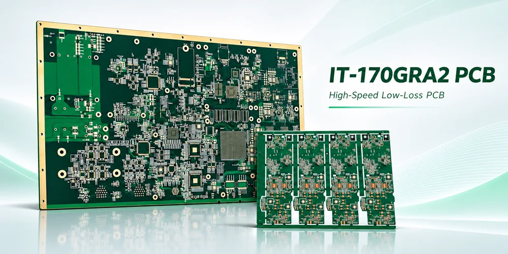
Illustration of high-speed PCB layouts.
ITEQ IT-170GRA2 is a halogen-free, high-Tg epoxy laminate and prepreg for lower-loss multilayer PCBs. ITEQ reports a dielectric constant (Dk) of 3.8 and a dissipation factor (Df) of 0.0080 at 10 GHz on a 50% resin-content specimen. That is a useful starting point for selecting a server, storage, networking or backplane stack-up. The decision to use it belongs to the channel loss budget.
Give the PCB its share of the channel loss budget
Start with a frequency-dependent limit and define the electrical reference planes. If the limit is specified from transmitter package to receiver package, reserve margin for the packages, connectors, launches, via transitions and fabrication variation before assigning the remaining loss to routed board traces. For a simple NRZ link, half the bit rate is the Nyquist frequency; for a multilevel link, use the symbol rate and the applicable specification. A single Nyquist checkpoint is useful for screening, but a production mask may cover a band and include return loss, crosstalk or mode conversion as separate requirements.
A first-pass loss allocation can add estimated positive loss contributions in decibels when the sections are well matched. Then cascade the actual transition and line models or measure the representative channel. Reflections can make the insertion-loss curve ripple, so the arithmetic budget is not a substitute for the cascaded result. Decide early which transitions belong to the board supplier’s test and which must wait until connectors or components are populated.
Compare the longest routed layer segments first. Where the dominant loss is in a long uniform trace, a lower-Df construction and a suitable foil may buy more margin. A short path with a deep plated via stub or a poorly referenced connector launch may benefit more from a layout change. In that second case, putting IT-170GRA2 into the same artwork may leave the main loss mechanism in place.
IT-170GRA2 Dk and Df by frequency
Usa il IT-170GRA2TC as the laminate designation and IT-170GRA2BS as the prepreg designation when reconciling the drawing with ITEQ’s data. ITEQ lists Tg as 175°C by DSC and 170°C by TMA. Neither value replaces component and solder-paste limits for assembly.
| Frequenza | Dk | Df | IPC-TM-650 method |
|---|---|---|---|
| 1 GHz | 4.0 | 0.0060 | 2.5.5.9 |
| 2 GHz | 3.9 | 0.0063 | 2.5.5.13 |
| 5 GHz | 3.9 | 0.0075 | 2.5.5.13 |
| 10 GHz | 3.8 | 0.0080 | 2.5.5.13 |
Fonte: ITEQ IT-170GRA2 datasheet, Rev. 1.0-26. The frequency points report test results; the table does not define a frequency limit for a product or a guaranteed loss per unit length.
How does it compare with IT-170GT? ITEQ reports 0.0095 Df at 10 GHz and 55% resin content for IT-170GT. The listed values point toward IT-170GRA2 when dielectric loss is the primary concern. They come from different resin contents, so applying the percentage difference directly to a finished channel would be misleading. Recalculate impedance and insertion loss for the proposed glass, pressed thickness and foil before approving a substitution.
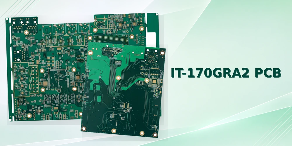
High-speed routing illustration. Evaluate channel loss on the specified stack-up and transitions.
Control the fabrication variables in the field model
Specify the copper surface that faces the dielectric
The smoothness of a foil label alone does not define conductor loss. The bonding treatment and roughness on the relevant copper surface change the current path when skin effect becomes significant. ITEQ’s sheet reports peel strength for a 35 µm low-profile foil reference; peel strength cannot be converted to the roughness parameters needed by a channel solver. Freeze the foil designation and treatment for the signal layer and its reference as applicable, and request roughness information compatible with the solver model. A change in rugosità del rame del PCB can move the loss curve while an impedance coupon still passes.
Keep the line and the discontinuities in the same release
Give CAM an impedance table by layer and reference plane, with finished copper thickness, pressed dielectric, differential gap and allowed artwork adjustments. The etched trace is often trapezoidal; the top and bottom widths need not match the artwork or each other. When there is impedenza controllata, a coupon should reproduce the relevant trace geometry and build. A long differential path can also see skew from local glass weave and routing orientation even when the average Dk and impedance look acceptable.
At the layer transition, evaluate the return-path change and the unused via barrel. A poorly placed return via or plane opening changes the transition; a stub can create a frequency-selective notch. Where backdrilling is contemplated, state the signal layer that must be protected, permissible residual stub and depth reference. Check these against both electrical sensitivity and the drill-depth tolerances agreed for the board.
FABBRICAZIONE E ASSEMBLAGGIO DI PCB
Planning an IT-170GRA2 PCB build?
Highleap può esaminare insieme i requisiti di costruzione e assemblaggio della scheda.
Include the target impedance, channel loss budget, reference test frequencies and any specified foil.
Richiedi una revisione della fabbricazione e dell'assemblaggio
Measure uniform trace loss separately from launches
Use TDR to locate impedance changes and confirm the line impedance profile. Use a calibrated VNA and an agreed S-parameter measurement to check insertion loss. For a differential line that may be mixed-mode Sdd21; agree on port mapping, normalization, calibration, de-embedding and the reference planes. Differences in launch layout or fixture handling can consume a significant fraction of a short coupon’s measured loss.
Hypothetical coupon calculation. At 10 GHz, a 50 mm trace coupon shows 1.4 dB of positive insertion loss and a 150 mm coupon shows 3.0 dB. With otherwise identical launches and matched uniform lines, the difference suggests about 1.6 dB per 100 mm for that construction at that frequency. Mismatches and fixture asymmetry can invalidate a simple subtraction, so compare the full traces and use the agreed extraction method. These values illustrate the calculation and do not describe an IT-170GRA2 test.
A line-loss coupon includes dielectric and conductor effects together. It does not isolate the resin’s Df, cover every routed layer or reproduce connector and via transitions unless those structures are deliberately included. For a failing first article, use time-domain localization and frequency-domain data together: broad excess attenuation along a uniform length points toward geometry or losses in the construction; a localized reflection or notch calls for checking the launch, return path or via. Neither symptom alone identifies a root cause.
Specify the bare-board and populated tests at quotation
Send the proposed stack-up, routed layer lengths, loss mask, impedance targets, foil requirements, coupon drawings and the electrical reference planes with your Highleap PCB fabrication and assembly inquiry. If the final channel includes populated connectors, add their part numbers, footprints, assembly requirements and any final-fixture definition. Highleap Electronics can review the fabrication inputs, quote assembly against the approved BOM and clarify which measurements belong at first article, at board release or after assembly. Confirm material availability and the measurement scope for the actual build before the design is frozen.

L'autore
Helen Chong
Consulente per soluzioni PCB e responsabile dello sviluppo commerciale all'estero presso Highleap Electronics
Helen supporta team di ingegneria internazionali con soluzioni complete di fabbricazione e assemblaggio di PCB, aiutando i progetti a passare da prototipi rapidi a una produzione di massa stabile. La sua esperienza spazia dalle schede ad alta frequenza e RF, agli stackup multistrato complessi, alle tecnologie PCB rigido-flessibili e flessibili in diversi settori.
Traducendo i requisiti tecnici in piani di produzione pratici, aiuta i clienti a migliorare la producibilità, ridurre i rischi e ottimizzare costi e tempi di consegna, mantenendo al contempo una qualità costante su larga scala.

Messaggi consigliati
Circuiti stampati per autoveicoli IT-858G per il controllo di potenza in rame pesante
Applicazioni dei PCB IT-858G nell'elettronica automobilistica e...
Scheda PCB IT-958G per server e backplane ad alta velocità
Esempi di PCB multistrato IT-958G per server e applicazioni ad alta velocità...
Scheda PCB IT-968GSE per reti ad alta velocità
Illustrazione del PCB IT-968GSE per interruttore a bassissima perdita e...
Realizzazione di schede IT-602G HDI per SSD e moduli di memoria
Esempi di PCB IT-602G per HDI, SSD e moduli di memoria...
Come ottenere un preventivo per i PCB
Eseguiamo un'analisi DFM/DFA per te e ti invieremo un report. Puoi caricare i tuoi file in modo sicuro tramite il nostro sito web. Per fornirti un preventivo, abbiamo bisogno delle seguenti informazioni:
-
- Specifiche Gerber, ODB++ o .pcb.
- Elenco BOM se è necessario l'assemblaggio
- Quantità
- Tempo di svolta
Oltre alla produzione di PCB, offriamo una gamma completa di servizi elettronici, tra cui progettazione di PCB, PCBA e soluzioni chiavi in mano. Che abbiate bisogno di supporto per la prototipazione, la verifica del progetto, l'approvvigionamento dei componenti o la produzione in serie, forniamo supporto completo per garantire il successo del vostro progetto.
Per i servizi PCBA, vi preghiamo di fornire la vostra distinta base (BOM) e le istruzioni di assemblaggio specifiche. Offriamo anche analisi DFM/DFA per ottimizzare i vostri progetti in termini di producibilità e assemblaggio, garantendo un processo produttivo fluido.