
柔性PCB加热器制造商,提供定制加热电路
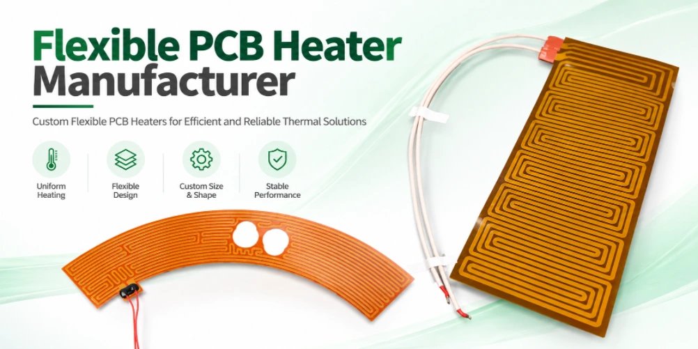
Custom flexible PCB heaters require coordinated electrical, thermal, material and mechanical design. Highleap Electronics can review your heater circuit data and project requirements to clarify the construction and information needed for a manufacturing quotation.
Flexible PCB Heater Construction and Circuit Layout
A flexible PCB heater uses a conductive pattern on a flexible substrate to generate heat when powered. The design must coordinate heater trace geometry, substrate, coverlay, electrical insulation, thermal spreading, mechanical flexing and mounting interface. Construction depends on temperature range, available area, supply voltage and duty cycle.
Distinguish a flexible printed heater circuit from a complete heating assembly that includes sensors, connectors, insulation or a metal spreader. If the project also needs assembly, discuss the overall scope with 柔性PCB组装服务 和 PCB assembly team.
A flexible PCB heater is not simply a standard flex circuit with a serpentine trace. The conductor pattern, substrate, coverlay, connector, mounting method, and thermal interface collectively determine how heat is generated and transferred. The layout must balance electrical resistance with mechanical robustness and the required active heating area. Tight turns, narrow trace necks, and abrupt changes in conductor width can create localized electrical or thermal stress, so the pattern should be reviewed as a functional heating element.
Define the non-heating zones, edge clearances, sensor locations, connector orientation, mounting holes, adhesive areas, and any regions that must remain flexible. If the heater will be bonded to a metal or polymer surface, specify the mating surface and the thermal contact method. A circuit tested in free air may behave differently after installation because heat transfer and thermal mass change the temperature distribution. The design should therefore distinguish bare-circuit requirements from final-assembly performance targets.
Materials, Coverlay and Temperature Requirements
Material selection should consider continuous and peak operating temperature, bend requirements, adhesive or adhesive-less construction, chemical exposure and attachment method. Polyimide is common in flexible circuits, but the exact material stack and temperature limits must match supplier data and the application.
Specify operating environment, thermal cycling, moisture or chemical exposure and cleaning process. The flexible substrate alone does not determine maximum working temperature; copper, adhesives, coverlay, connectors and mounting interface can each be limiting factors.
Material selection should begin with the operating environment rather than a single maximum-temperature number. Consider continuous operating temperature, short-term excursions, thermal cycling, humidity, chemical exposure, cleaning agents, and the mechanical movement expected during service. Polyimide is commonly used for flexible circuits, but the full construction may also include adhesive layers, coverlay, stiffeners, pressure-sensitive adhesive, solder, and connector materials that have different limits.
Specify the required copper type and thickness, dielectric construction, coverlay openings, adhesive system where applicable, and any restrictions on materials. If the heater will be used near liquids, skin contact, food, medical equipment, or other regulated environments, the product-level requirements need separate review; a PCB material choice alone does not establish regulatory compliance. For a design that needs repeated flexing, the material and copper construction should be selected with the bend location and cycle count in mind.
Heater Resistance, Power and Temperature Uniformity
Electrical power relates to voltage and resistance, but resulting temperature also depends on heat loss, substrate contact, airflow, thermal mass and surrounding materials. Review the heater pattern for current density, local hot spots, trace spacing, connector loading and expected resistance tolerance.
Provide target voltage, nominal resistance or power, allowed resistance variation, active heating area, target temperature, warm-up time and control method. If uniform heating matters, state the measurement method and allowable temperature variation.
1. Convert the heating requirement into an electrical specification
Start with the system requirements rather than drawing a serpentine trace immediately. Define the supply voltage, desired nominal power or resistance, active heating area, target temperature, warm-up time, ambient conditions and how the heater will be controlled. For a resistive element, the basic relationships are power equals voltage squared divided by resistance, and power equals current squared multiplied by resistance. These relationships help set an initial electrical target, but they do not predict final surface temperature without a thermal model or representative test.
State whether the resistance is a room-temperature nominal value, a value at operating temperature, or a value measured under a specified test condition. Copper resistance changes with temperature, and the assembled system may have contact resistance at connectors or terminals. If the heater is driven by a constant-voltage supply, resistance variation changes current and power; if it is driven by a controlled current or closed-loop controller, the behavior differs. The control architecture must therefore be part of the design discussion.
2. Design the trace pattern for power distribution
The trace pattern determines how electrical power is distributed over the active area. Trace width, spacing, length, copper thickness, bends, terminal geometry and local heat loss all influence resistance and temperature distribution. A narrow trace or crowded turn can produce a local hot spot, while a broad low-resistance path may deliver less heat than intended in a region. The pattern should be evaluated as a whole, including the feed paths and transition from connector pads to the active heater.
Do not judge uniformity from the visual regularity of the serpentine pattern alone. Edge losses, mounting contact, nearby metal, airflow and insulation can make the same electrical pattern behave differently in different assemblies. Provide the actual mounting arrangement and surrounding materials, and identify zones that must remain cooler or reach a particular temperature. If multiple heating zones are required, show their electrical separation and control strategy.
3. Define temperature uniformity and test conditions
“Uniform heating” is not a complete acceptance criterion. Specify the measurement area, sensor type or measurement method, ambient temperature, applied voltage or power, stabilization time, mounting pressure, thermal interface and allowable temperature variation. If the requirement is a maximum temperature at a defined point, identify that point and the worst-case operating condition. A test performed on an unsupported flex circuit may not represent performance after it is bonded to a housing or spreader.
Thermal validation should consider both steady-state and transient behavior when these matter to the product. Warm-up time, overshoot, cool-down, repeated on/off cycling and response to loss of thermal contact may all be relevant. If a sensor or thermostat is included, clarify whether it is part of the flexible PCB, a separate component, or supplied by the customer. The heater PCB manufacturer can fabricate the circuit to the agreed specification, but system-level temperature performance must be validated in the intended assembly.
4. Consider electrical protection and abnormal conditions
Document the normal operating voltage and current, maximum permitted input, expected duty cycle and any abnormal conditions that the finished product must tolerate. Depending on the application, the complete system may need current limiting, over-temperature protection, a temperature sensor, a fuse or a controller response to sensor failure. These functions should not be assumed to be provided by the copper pattern itself.
Identify the required insulation, creepage or clearance constraints where applicable, as well as the environmental exposure and mechanical protection. If the heater is used near a battery, skin-contact surface, fluid, or combustible material, the product-level risk analysis and applicable safety requirements need to be addressed by the responsible system designer. State the test evidence and documentation required from the PCB supplier, and separate it from any certification required for the complete product.
5. Resistance tolerance, material variation and production control
Set a nominal resistance and an acceptable tolerance that accounts for trace geometry, copper thickness, etching variation, material effects and measurement conditions. If resistance is the primary acceptance parameter, define the measurement temperature, test current or method, connector contact points and whether the measurement is performed before or after adding the connector or other assembly parts. A tolerance that is too narrow for the chosen construction may increase cost or require a different pattern or process review.
For a production quotation, include the required electrical test and lot records. If temperature uniformity is critical, identify whether the supplier is expected to perform a thermal test on every unit, on samples, or only during qualification. These are very different inspection scopes. The most effective brief links the circuit geometry, electrical target, mounting conditions and validation method into one specification so the manufacturer can identify missing information before production.
Electrical design starts with the required supply voltage and target resistance or power. For a resistive element, power depends on voltage and resistance, but the temperature achieved in use also depends on the surface being heated, thermal contact, insulation, airflow, ambient conditions, and control behavior. The same electrical design can produce different temperatures when installed on different substrates or operated under different boundary conditions.
To assess uniformity, define the active heating area, target temperature range, measurement points, stabilization time, and allowed variation. Include any sensor position, control loop, and over-temperature response that the system requires. The trace pattern should be checked for current concentration at corners and transitions, connector heating, and areas where adjacent traces may create a temperature gradient. A thermal test plan should state the mounting method and operating conditions so the result is reproducible.
Bend Radius, Mounting and Mechanical Reliability
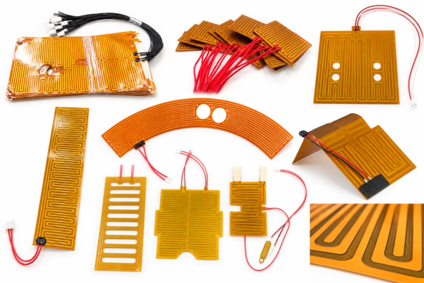
A flexible heater may be static-flex or dynamic-flex. Repeated bending can fatigue copper and stress transitions, while mounting pressure and thermal expansion can affect performance. Define minimum bend radius, bend direction, expected cycle count and keep-out zones.
Provide mechanical outline, mounting holes or adhesive zones, connector position and stiffener details. For combined flexible and rigid regions, review whether a 定制PCB制造 route or rigid-flex construction is appropriate.
Static-flex and dynamic-flex applications should be specified differently. A static-flex heater may be formed once during installation, while a dynamic-flex heater experiences repeated movement. Repeated bending can strain copper and create fatigue, particularly near stiffener edges, connectors, solder joints, or abrupt changes in construction. The drawing should show the bend line, bend direction, minimum radius, and any zones where components, vias, or stiffeners are not permitted.
Mounting also affects reliability and temperature behavior. Adhesive thickness, clamping pressure, surface flatness, and thermal expansion can change both heat transfer and mechanical stress. If the heater is bonded to a curved part, provide the radius and expected forming method. If it is attached using screws or clips, identify the load points and clearance requirements. These details allow the supplier to review the flexible circuit as part of its real mechanical environment rather than as a flat outline only.
Electrical, Thermal and Safety Validation
Acceptance criteria should address continuity, insulation requirements, resistance, temperature behavior and operating conditions. Depending on the product, validation may include temperature mapping, thermal cycling, dielectric testing or functional testing in the final assembly.
Define who is responsible for heater control, over-temperature protection, sensor integration and system-level safety evaluation. PCB fabrication alone does not certify the completed heating product to a particular regulatory standard.
Validation should separate the electrical checks on the flexible circuit from the thermal and safety evaluation of the finished product. Bare-circuit checks may include continuity, resistance, insulation, and visual inspection. Thermal validation may require temperature mapping at defined voltage, mounting, ambient, and stabilization conditions. Depending on the application, further checks may include thermal cycling, flex cycling, moisture exposure, or testing after mechanical installation.
Define the required records before production: resistance limits, insulation test conditions, thermal map locations, sample quantities, pass/fail criteria, and traceability expectations. System-level protection such as a thermostat, temperature sensor, fuse, or electronic cutoff must be assigned clearly to the product design. PCB fabrication alone cannot guarantee safe operating temperature under every possible fault or installation condition, so the system owner must define and validate the complete protection strategy.
What a Flexible PCB Heater Manufacturer Needs to Quote
Send the outline drawing, Gerber or ODB++ files, stack-up and material requirements, copper thickness, heater resistance or power target, operating voltage, target temperature, active area, coverlay, connector details, bend conditions, quantity and delivery target.
If the design is still developing, provide electrical and thermal targets and identify which values are fixed. Request a quote through the PCB报价请求. If component sourcing or assembly is required, review 交钥匙PCB组装 和 PCB组装服务.
A useful RFQ includes the circuit outline, fabrication data, stack-up, copper thickness, material and coverlay requirements, operating voltage, target resistance or power, active heating area, temperature target, bend conditions, connector details, mounting method, quantity, and required delivery date. State whether the temperature target applies to the heater surface, the mating part, or a defined measurement point. If the design has a maximum temperature, specify the test conditions and whether it is a normal operating limit or a fault condition.
If the circuit is not finalized, submit a functional specification and mechanical drawing first. Identify the parameters that are fixed and the ones open to design optimization, such as resistance, trace layout, connector location, or outline. For an assembled product, include the sensor or control components, BOM, placement data, and functional test requirements. This makes it possible to evaluate whether the request is for a flex circuit only or a broader assembly and validation package.
常見問題解答
Can a flexible PCB heater bend during operation?
That depends on whether the construction is designed for static or dynamic flexing. Specify bend radius, cycle count and mounting conditions for review.
Can you guarantee a specific surface temperature?
Surface temperature depends on electrical input, control strategy, thermal contact, environment and finished assembly. Define test conditions and acceptance limits.
What details are essential for a quote?
Provide voltage, resistance or power target, operating temperature, active area, substrate and coverlay, bend conditions, outline, quantity and delivery target.
Discuss Your Flexible PCB Heater Manufacturer Project
请提供最新的 Gerber 文件、叠层图或机械图、制造说明、数量、目标日期和验收标准。我们将审核您提供的信息,并确定报价所需的详细信息。
索取 PCB 报价添加PCB组装工程注意事项:可制造性、可实现尺寸、公差、材料、检验方法和交货周期取决于具体的设计和生产评审。在发布前,请务必确认已批准的制造方案中的关键要求。

推荐文章
中国14层PCB制造商
定制刚性多层PCB板 Highleap Electronics...

14层PCB组装和一站式PCB制造
PCB制造 + PCBA Highleap Electronics 提供 14...

高性能电子产品用氮化铝陶瓷PCB制造商
海跃电子 · 氮化铝陶瓷PCB…

氧化铝PCB制造,适用于OEM原型和生产
海跃电子 · 氧化铝陶瓷PCB制造...
如何获取 PCB 报价
我们将为您进行 DFM/DFA 分析,并向您提供报告。您可以通过我们的网站安全地上传文件。我们需要以下信息才能为您提供报价:
-
- Gerber、ODB++ 或 .pcb,规格。
- 如果需要组装,请提供 BOM 清单
- 数量
- 转弯时间
除了 PCB 制造,我们还提供全面的电子服务,包括 PCB 设计、PCBA 和交钥匙解决方案。无论您需要原型设计、设计验证、元器件采购还是量产方面的帮助,我们都提供端到端支持,确保您的项目成功。
如需 PCBA 服务,请提供您的 BOM(物料清单)和任何具体的装配说明。我们还提供 DFM/DFA 分析,以优化您的设计,提高可制造性和装配性,确保生产流程顺畅。