
10vrstvá pravidla směrování desek plošných spojů pro DDR5, PCIe a Crosstalk

Obrázek 1. Pravidla směrování 10vrstvých desek plošných spojů pro DDR5 PCIe a přeslechy.
Obsah
- Před zahájením trasování zmrazte elektrická pravidla
- Přiřazení vrstev a kontinuita návratové cesty
- Diferenciální páry: geometrie, šikmost a přechody
- DDR5 a další paralelní paměťová rozhraní
- PCIe a vysokorychlostní sériové linky
- Přeslechy, rozteče a šum v referenční rovině
- Ladění délky bez vytvoření nové diskontinuity
- BGA únik, průchody a vyrobitelnost
- Kontrola předvýrobního trasování
- Spuštění konektorů, hranice desky a testovací struktury
- Hranice směrování hodin, analogových signálů a napájení
- Potvrzení směrovacího pravidla
- Správa výjimek směrování
Pravidla směrování pro desetivrstvou desku plošných spojů by měla být odvozena ze struktury, průvodců návrhem součástek a analýzy kanálů. Neměla by být kopírována z obecné tabulky hodnot v mil. Stejná fyzická délka neznamená vždy stejné elektrické zpoždění, „pravidlo 5 W“ není zárukou přeslechů a generování protokolu automaticky neurčuje laminát nebo pevný reziduál přes pahýl.
Účelem této příručky je přeměnit elektrické požadavky na omezení rozvržení, která zůstanou platná po celou dobu výroby. Zaměřuje se na zpětné cesty, propojené směrování, časování paměti, přechody sériového spojení, přeslechy a předávání do DFM. Konečné šířky a mezery pocházejí z uvolněného impedanční model.
Před zahájením trasování zmrazte elektrická pravidla
Směrování by nemělo začínat provizorními dielektrickými tloušťkami a končit požadavkem, aby výrobce „upravil souvrství tak, aby odpovídalo“. Změna souvrství mění šířku, rozteč párů, zpoždění šíření, přiřazení referencí a někdy i kapacitu vrstev. Balíček základních parametrů by měl identifikovat revizi souvrství, materiálovou konstrukci, měď, řízené struktury, pravidla časování specifická pro dané zařízení a elektrické modely použité pro kritické kanály.
| Skupina omezení | Zdroj pravdy | Výstup rozvržení |
|---|---|---|
| Geometrie impedance | Vydán výpočet stackup a fabricator/field-solver. | Šířka, párová mezera, koplanární vůle, stav masky a povolený neck-down. |
| Načasování/zkosení | Průvodce návrhem řadičů, pamětí, fyzických obvodů nebo konektorů a simulace. | Maximální zpoždění nebo zkreslení podle skupiny signálů, nikoli nevysvětlitelná univerzální hodnota mil. |
| Ztráta/dosah | Maska protokolu nebo zákaznického kanálu a extrahovaný model. | Přiřazení vrstev, maximální délky trasy, počet přechodů a potřeba materiálu. |
| Přeslech | Citlivost oběti a studie řešitele pole/kanálu. | Omezení roztečí nebo rovnoběžnosti podle vrstvy a třídy agresora. |
| Prostřednictvím přechodu | 3D model nebo ověřená knihovna pad-stacků. | Vrtání, ploška, protiploška, uspořádání zemních průchodů, rozpětí vrstev a zpětné vrtání. |
| Výroba | Dodavatelské schopnosti pro přesnou desku. | Minimální geometrie, prstenec, registrační přídavek, maskovací přepážka a vyvážení mědi. |
Používejte hierarchii pravidel. Požadavky specifické pro zařízení nebo tvarový faktor mají přednost před obecným pravidlem společnosti; simulovaná výjimka by měla být zdokumentována; a výrobní minima jsou limity, nikoli preferované rozměry trasy.
Přiřazení vrstev a kontinuita návratové cesty
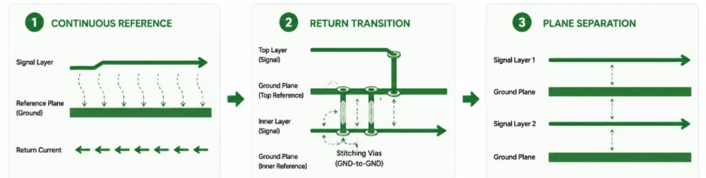
Každá vysokorychlostní trasa potřebuje spojitý referenční vodič. U běžného desetivrstvého uspořádání zaměřeného na integritu signálu odkazují vnější signály na sousední zemní roviny a vybrané vnitřní signály jsou umístěny mezi dvěma zemními rovinami. Toto uspořádání je užitečné, protože zpětný proud může zůstat blízko signálu. Jiná uspořádání mohou fungovat, ale pravidla uspořádání musí odrážet jejich skutečné reference.
Nesměrovat přes rozdělení reference
Když trasa protne dutinu nebo rozdělení v referenční rovině, zpětný proud obchází otvor, čímž se zvětší plocha smyčky a dojde k propojení s jinými strukturami. Přesunutí trasy do vrstvy se spojitou referencí je obvykle lepší než přidání kondenzátoru po rozvržení. Pokud je napájecí rovina záměrně použita jako vysokofrekvenční reference, musí být její připojení k příslušné zemní doméně součástí návrhu.
Změny vrstev vyžadují návratový přechod
Signální průchodka přesouvá proud vpřed mezi vrstvami; návratový proud také potřebuje cestu mezi starou a novou referencí. Přechody mezi zemí a zemí běžně používají blízké propojovací průchodky. Přechody mezi napájením a zemí mohou vyžadovat oddělovací strukturu umístěnou tak, aby návratová smyčka byla v relevantním spektru přijatelně malá. „Jeden zemnící průchod do 50 mil“ je heuristika, nikoli univerzální pravidlo.
Sousední signálové vrstvy
Ortogonální směrování může snížit vazbu mezi sousedními signálovými vrstvami, ale neznamená to, že je inherentně špatně definované vrstvení neškodné. Pokud jsou dvě signálové vrstvy proti sobě a mezi nimi není žádná rovina, omezte překrývání, zvětšete oddělení a rezervujte dvojici pro méně citlivé sítě. Pro kritické sériové linky je vhodnější směrování oddělené rovinami.
Diferenciální páry: geometrie, šikmost a přechody
Diferenciální pár vodičů by měl zachovat konzistentní elektromagnetické prostředí. Šířka, rozteč párů, referenční vzdálenost a blízké měděné vodiče by měly zůstat v rámci struktury použité pro výpočet impedance. Krátké zúžení kontaktních plošek může být nevyhnutelné, ale mělo by být modelováno nebo udržováno v rámci validovaného rozměru.
Vnitropárová zkosenost je elektrická veličina
Převeďte povolenou časovou šikmost na délku s využitím skutečného zpoždění šíření na směrované vrstvě. Dvojice, která mění vrstvy, může mít stejnou fyzickou délku, ale nestejné zpoždění, pokud obě stopy vzorkují různé sklo, používají různou geometrii průchodů nebo narážejí na různé referenční přechody. U velmi rychlých spojů extrahujte zpoždění a konverzi módů, spíše než se spoléhejte pouze na délku středové čáry nástroje pro výrobu desek plošných spojů.
Udržujte oba přechody symetrické
Signální propojovací kontakty, antipropojovací kontakty, referenční propojovací kontakty a rozdělovací kontakty by měly být pokud možno zrcadlově symetrické. Vyhněte se umisťování jedné stopy blíže k rovinnému prázdnému místu, montážnímu otvoru nebo stínění konektoru. Pokud rozhraní umožňuje inverzi polarity, použijte ji záměrně, místo abyste přidali dlouhý výhybkový vodič, abyste zachovali vizuální orientaci.
Párové párování není automaticky vyžadováno
Mnoho sériových přijímačů vychyluje dráhy, takže vynucení stejné fyzické délky všech párů PCIe nebo SerDes může způsobit zbytečné ztráty a meandry. Dodržujte platný požadavek na zkreslení mezi dráhami, ale upřednostňujte nízké ztráty, čisté návratové cesty a minimální přechody. Zkreslení v rámci páru je obvykle důležitější než porovnávání nesouvisejících drah.
DDR5 a další paralelní paměťová rozhraní
Omezení DDR5 závisí na pouzdře řadiče, organizaci DRAM, topologii modulů nebo downgradu, rychlostním intervalu, načítání a zakončení. Správným zdrojem je návrhová příručka dodavatele řadiče a paměti, podpořená simulačními modely. Obecné prohlášení jako „DQ musí odpovídat +/- 5 mil“ může být pro konkrétní platformu buď zbytečně striktní, nebo nebezpečné.
Seskupení pravidel podle funkce
Definujte samostatné skupiny pro DQ/DMI vzhledem k DQS, diferenciálnímu hodinovému signálu, signálům příkazů/adresy/řízení a všem signálům specifickým pro modul. Pokud je to možné, použijte omezení zpoždění v pikosekundách, protože fyzická délka se na různých vrstvách převádí odlišně. Nástroj pro rozvržení pak může použít zpoždění specifické pro danou vrstvu, místo aby předpokládal jednu konstantu šíření.
Topologie je důležitá
Příkaz/adresa a hodiny mohou v modulově orientovaných provedeních používat topologii typu „fly-by“, zatímco datové signály jsou zdrojově synchronní dvoubodová spojení v rámci bajtové dráhy. Konstrukce s nulovým napájecím proudem, registrované moduly a moduly s bufferem zavádějí odlišné zatěžování a směrování. Nekopírujte topologii DIMM na pájenou konstrukci bez dokumentace platformy.
Referenční a výkonová integrita
Časování paměti je ovlivněno šumem v referenční rovině a rozložením výkonu, stejně jako délkou stopy. Udržujte bajtové dráhy ve stabilním referenčním prostředí, zajistěte vhodné ošetření VREF a VDDQ a vyhněte se umisťování ladicích struktur přes otvory v rovině. Simulujte současné přepínání a ukončení, když je rezerva platformy omezená.
PCIe a vysokorychlostní sériové linky
U PCIe Gen5 a novějších je kvalita trasy dominována frekvenčně závislými ztrátami, nespojitostmi konektorů a propojení, přeslechy a konverzí módů. Sada pravidel rozvržení by proto měla zahrnovat více než jen cílovou impedanci.
| Kategorie pravidel | Praktický požadavek |
|---|---|
| Přiřazení vrstev | Použijte vrstvu a materiál reprezentovaný modelem kanálu; vyhněte se nemodelovaným záměnám povrchu/vnitřní vrstvy. |
| Počet přechodů | Minimalizujte změny vrstev a spouštění konektorů, ale nevyměňujte čistou referenci za kratší trasu. |
| Průchozí struktura | Použijte ověřený vzor pro padky/antipadky a zpětné provrtání; v případě potřeby definujte rozpětí zpětného vrtání nebo zaslepení. |
| Párové zkosení | Použijte specifikaci nebo simulační limit v čase; udržujte průraz a ladění symetrické. |
| Rozestupy jízdních pruhů | Nastaveno z analýzy přeslechů a paralelní délky, nejen slogan s násobkem šířky. |
| Testovací přístup | Nepřidávejte neukončené pahýly. Používejte ověřené testovací struktury nebo přístup založený na konektorech. |
| AC spojka | Dodržujte pokyny pro umístění zařízení/tvarového faktoru a rozměry komponent; udržujte symetrické prostředí páru. |
PCIe 6.0 používá PAM4 s rychlostí 64 GT/s a stejnou Nyquistovou frekvencí 16 GHz jako PCIe 5.0 NRZ, ale nejedná se o „stejný kanál s dvojnásobným počtem bitů“. Liší se kontext kompatibility, šumu a FEC. PCIe 7.0 s rychlostí 128 GT/s posouvá Nyquistovu frekvenci na 32 GHz a ztěžuje extrakci přechodů a korelaci výroby.
Přeslechy, rozteče a šum v referenční rovině
Často uváděné pravidlo 3W nebo 5W je geometrická heuristika. Přeslechy také závisí na dielektrické výšce, délce paralelních vodičů, době náběhu agresoru, referenční struktuře a na tom, zda jsou vodiče propojeny hranou nebo bočním vedením. Na tenkém dielektriku může menší rozteč již splňovat cíl; na sousedních nereferenčních signálových vrstvách může být velká rozteč stále nedostatečná.
Nastavte cíl přeslechu vhodný pro rozhraní a použijte extrakci nebo validovanou geometrickou tabulku k převedení tohoto cíle na rozteč. Zohledněte celkovou délku oběti a simultánní agresory. Jednostranné sítě s hodinovým, stroboskopickým a vysokofrekvenčním signálem si mohou zasloužit větší izolaci než nesouvisející pomalé ovládací prvky.
Šum v rovině se může prolínat referenční strukturou, i když je mezi jednotlivými stopami dostatečná vzdálenost. Udržujte spínací smyčky s vysokým proudem kompaktní, používejte vhodné páry rovin a oddělení a vyvarujte se nuceného připojování citlivých stop k fragmentovaným napájecím ostrovům. Přeslechy a integrita napájení by měly být u procesorů s vysokou hustotou a akceleračních desek posuzovány společně.

Obrázek 2. Směrování a rozvržení zpětné cesty na 10vrstvé desce plošných spojů.
Ladění délky bez vytvoření nové diskontinuity
Meandry přidávají zpoždění, ale blízko sebe umístěné segmenty se vzájemně propojují a způsobují menší zpoždění, než naznačuje délka jejich středové čáry. Také zvyšují ztráty a vytvářejí lokální kolísání impedance. Použijte co největší praktickou vzdálenost mezi sousedními ladicími segmenty, minimalizujte počet otáček a rozložte ladění tam, kde nenarušuje průrazy nebo kontinuitu reference.
Neexistuje univerzální pravidlo, že ladění musí být blízko zdroje nebo blízko přijímače. Umístění závisí na topologii a účelu sladění. U synchronní sběrnice zdroj-přijímač laďte v rámci definované skupiny a zachovávejte topologii. U diferenciálního páru korigujte zkosení kompaktním, symetrickým prvkem, který nevytváří dlouhou nesouvislou část.
Zaoblené rohy nejsou automaticky vyžadovány a jediný ohyb o 90 stupňů nepředstavuje 15% odraz v každé geometrii. Pro vyrobitelnost, párovou symetrii a konzistentní rozteč použijte 45stupňové nebo zakřivené trasování, ale zaměřte se na větší nespojitosti, jako jsou kontaktní plošky, prostupy, konektory a přerušení referenční roviny.
BGA únik, průchody a vyrobitelnost
Samotná rozteč BGA neurčuje, zda je vyžadováno připojení přes HDI. Záleží na průměru kontaktů, strategii pájecí masky, počtu řad, mapě pinů, dostupných vrstvách směrování a směru úniku. Některé součástky s roztečí 0.5 mm mohou používat pečlivě navržený přístup s průchozími nebo omezenými zaslepenými kontakty; jiné vyžadují kontakty v kontaktech a více vrstev. Zkontrolujte skutečné rozvětvení pouzdra, místo abyste používali pouze tabulku roztečí.
V popisku propojovací plošky by mělo být uvedeno, zda je propojovací otvor vyplněn mědí, vyplněn pryskyřicí a zakryt, nebo zda je ošetřen jiným kvalifikovaným postupem. U vrstvených mikroproudů musí být dohodnuta postup montáže a plán spolehlivosti. Průvodce HDI zahrnuje výběr struktury; uspořádání musí stále poskytovat záchytné plochy, protilehlé plochy a ochranné pásy kompatibilní s registračními možnostmi dodavatele.
Únikové směrování by mělo také zachovat kontinuitu referencí. Hustá pole proti kontaktům mohou odstranit příliš mnoho rovinné mědi pod pouzdrem, takže napájecí a zemnící průchodka by měla být posuzována jako elektromagnetická struktura. Přidání dalších zemních průchodů není vždy výhodné, pokud vynucuje vznik nadměrně velkých dutin nebo brání směrování.
Kontrola předvýrobního trasování
| Zkontrolovat položku | Otázka k vydání |
|---|---|
| Revize zásobníku | Odkazují všechna pravidla a simulace přesně na citovaný stackup? |
| Řízené struktury | Jsou přiřazení šířky, rozteče, masky a vrstev propojena s tabulkou impedance? |
| Zpáteční cesty | Má každá kritická trasa a změna vrstvy nepřetržitou zpětnou cestu? |
| Načasování | Jsou limity převzaty ze skutečného zařízení/topologie, nejlépe v čase, spíše než zkopírované hodnoty v mil? |
| Ztráta a přechody | Jsou kritické trasy extrahovány s vybranými modely materiálu, mědi a propojení/konektorů? |
| Přeslech | Jsou pravidla pro rozestupy vázána na cílovou a rovnoběžnou délku? |
| Únik z BGA | Je konstrukce průchodu vyrobitelná a vhodná pro zvolenou konstrukci? |
| Měděná bilance | Splňují frézování a lití požadavky na deformaci a pokovování pro skládání? |
| Autorita DFM | Je jasné, jaké změny v grafickém díle může zhotovitel provést bez souhlasu? |
DFM revize by neměla potichu přepisovat elektrická omezení. Pokud CAM navrhne změnu šířky, kontaktní plochy, anti-padu nebo vrstvy, měla by být tato změna porovnána s impedančním nebo kanálovým modelem a zdokumentována. Odešlete finální rozvržení s výrobním výkresem a netlistem prostřednictvím Proces přezkumu DFM.
Spuštění konektorů, hranice desky a testovací struktury
U konektorů jsou často větší diskontinuity než běžné ohyby. Zkontrolujte signální plošku, antiplošku, rozložení zemnicích pinů, výřezy v rovině a přechod do směrovaného páru jako jednu strukturu. Stopy od dodavatele jsou výchozím bodem, nikoli zárukou, protože tloušťka desky, přiřazení vrstev a výrobní rozměry se mohou lišit. U konektorů s nejvyšší rychlostí použijte model dodavatele a extrahujte lokální uzávěr desky plošných spojů.
Na okrajích desky se vyhněte náhlému ukončení referenční roviny pod citlivou trasou. Kontakty na okraji desky, koaxiální kabely a mezaninové konektory mohou vyžadovat uzemnění pomocí plotů nebo lokálních přechodů vrstev, které jsou specifické pro dané rozhraní. Udržujte mechanické zábrany, pokovovací lišty a oddělovací jazýčky mimo oblast elektrické reference, pokud nejsou zahrnuty v modelu.
Navrhněte testovací přístup bez vytváření stubů
Běžné testovací plošky a rozvětvené testovací body mohou zvyšovat kapacitu nebo vést k neukončenému odbočce. Použijte ověřený testovací kupón, přístup ke konektoru, možnost vyměnitelných součástek nebo plošku integrovanou do hlavní přenosové cesty. Před dokončením rozvržení koordinujte požadavky na testování v obvodu s integritou signálu; odstranění testovací větve po kvalifikaci může také změnit kanál.
Dokumentace úmyslných výjimek
Husté rozvržení někdy vyžaduje lokální změnu šířky, přechod reference nebo narušení rozteče. Zaznamenejte umístění, důvod a simulaci nebo schválení dodavatelem. Zdokumentovaná výjimka je bezpečnější než globální uvolnění pravidla nebo spoléhání se na budoucího DFM inženýra, aby odvodil záměr návrhu.
Hranice směrování hodin, analogových signálů a napájení
Ne každá důležitá síť je diferenciální sériová linka. Referenční hodiny, resetovací signály, analogové dráhy senzorů a uzly spínaného napájení mohou vytvářet nebo přijímat rušení. Sítě klasifikujte podle frekvence hran, citlivosti na šum a proudové smyčky, nikoli pouze podle nominální frekvence. Nízkofrekvenční hodiny s rychlou hranou mohou vyžadovat více péče než sinusová vlna s vyšší frekvencí.
Referenční hodiny
Referenční hodiny veďte přes spojitou rovinu, vyhněte se zbytečným testovacím pahýlům a izolujte je od přepínacích uzlů. Požadovaná topologie – bod-bod, vyrovnávací paměť s rozvětvením nebo jiná metoda distribuce – vychází ze specifikací zdroje hodin a přijímače. Hvězdicové nebo řetězové zapojení není univerzálně správné. V případech, kdy je řízeno více přijímačů, simulujte zatížení a ukončení.
Analogová a převodní rozhraní
Udržujte malé analogové smyčky kompaktní a oddělte je od agresivních digitálních návratových proudů. Rozdělení zemní roviny není automaticky výhodné; souvislá rovina s promyšleným umístěním často poskytuje návrat s nižší impedancí. Pokud se analogová a digitální doména musí spojit v kontrolovaném bodě, zajistěte, aby signály nepřekračovaly výslednou mezeru a aby strategie připojení odpovídala pokynům dodavatele převodníku.
Přepínání výkonových regionů
Přepínací uzel, smyčka hradlového budiče a proudové cesty s vysokým di/dt si zaslouží fyzické vyloučené zóny. Neveďte vysokorychlostní páry pod induktory, transformátory ani měděnými vodiči přepínacího uzlu. V analýze zpětné cesty by se měly zohlednit prázdné prostory v rovině a uzavřené prostory. Šířka vedení proudu a tepelné vlastnosti by měly být vyhodnoceny metodami IPC-2152 nebo validovanou simulací, spíše než univerzálním číslem proudové hustoty.
Zdokumentujte tyto oblasti v omezeních rozvržení, aby se přídavky mědi DFM, odlupování nebo prvky panelů neúmyslně nedostaly do citlivé oblasti.
Potvrzení směrovacího pravidla
Závěrečná kontrola směrování by měla porovnat rozvržení s vydaným stackupem a omezeními specifickými pro dané zařízení, spíše než s obecným kontrolním seznamem mil hodnot. Kritické skupiny by měly být kontrolovány pomocí extrahovaných modelů zpoždění, ztrát a přechodů, pokud jsou tyto vlivy významné.
- Ověřte, zda každá kritická trasa zůstává nad spojitou referencí a zda změny vrstev poskytují cestu zpětného proudu.
- Zkontrolujte diferenciální geometrii pomocí zdířek, kontaktních plošek, prostupů, konektorů a testovacích struktur – nejen na přímých drahách.
- Použití časování paměti podle bajtové dráhy, skupiny příkazů/adres a topologie s využitím dokumentace k řadiči a paměti.
- Omezte meandry a paralelismus na základě analýzy zpoždění a přeslechů, spíše než na univerzálním multiplikátoru rozteče.
- Ověřte, zda rozvětvení BGA, prstencové kroužky, protilehlé kontakty a rozpětí propojení odpovídají schváleným možnostem dodavatele.
- Dodávejte finální grafické návrhy, seznam sítí, data pro vrtání/trasování, revizi vrstvených struktur, tabulku impedancí a výkres s řízenou hloubkou jako jeden balíček s řízenou revizí.
Pravidla rozvržení by měla vyjadřovat elektrický cíl a jeho zdroj. To umožňuje kontrolu výjimek a zabraňuje tomu, aby změna ve výrobě tiše zneplatnila sadu omezení trasování.
Správa výjimek směrování
Husté rozvržení nevyhnutelně potřebuje výjimky z preferovaných pravidel. Cílem není zakázat každé zmenšení krku, přechodu mezi vrstvami nebo lokální zmenšení rozteče; jde o to identifikovat, které výjimky jsou elektricky významné, a posoudit je pomocí správného modelu.
| Výjimka | Metoda kontroly | Důkazy o uvolnění |
|---|---|---|
| Krátký BGA krk dolů | Modelujte lokální impedanci a délku; ověřte leptání a maskování. | Maximální délka, šířka/mezera a ovlivněné vrstvy v sadě pravidel. |
| Přechod referenční roviny | Zkontrolujte smyčku zpětného proudu a cestu sešívání/oddělování. | Ověřený vzor propojovacího pole nebo zdokumentované lokální rozvržení. |
| Snížená vzdálenost mezi páry | Extrahujte přeslechy pro skutečnou délku paralelního signálu a aktivitu agresora. | Povolená délka a umístění, nikoli globální výjimka. |
| Další meandr | Zkontrolujte zpoždění, samočinnou vazbu a přidané ztráty. | Minimální rozteč otáček a maximální hustota ladění. |
| Nevyhnutelné přes stub | Modelujte rezonanci a porovnejte ji s alternativami s vrtáním zpět nebo se zaslepením otvorů. | Schválený rozsah vrstev a požadavek na zbytkový pahýl. |
Výjimky by měly být připojeny k sítím, regionům nebo třídám a uloženy v záznamu o přezkoumání návrhu. Obecné slovní schválení, jako například „rozteč je přijatelná“, nelze reprodukovat během ECO nebo přenosu dodavatele. Stejný princip platí pro rozvržení referencí dodavatele zařízení: zachovat elektrický záměr, ale znovu ověřit rozměry oproti uvolněnému uspořádání desek.
Záznam o kontrole by měl také identifikovat verzi extrakce nebo simulace použitou pro kritické výjimky. Když ECO přesune komponentu, změní vrstvu nebo pozmění rozložení konektoru, lze dotčenou výjimku znovu vyhodnotit, místo aby se zdědilo schválení, které již neodpovídá geometrii.

doporučené příspěvky

Výroba desek plošných spojů Taconic RF-35 – od prototypů až po sériovou výrobu
Obrázek 1. Deska plošných spojů Taconic RF-35 Taconic RF-35 je pracant...

Výroba desek plošných spojů Isola Astra MT77
Obrázek 1. Výroba desek plošných spojů Isola Astra MT77 Isola Astra...

Zakázkové služby výroby a montáže desek plošných spojů Rogers RO4835
Obrázek 1. Deska plošných spojů Rogers RO4835Deska plošných spojů Rogers RO4835 je...

Průvodce materiálem a výrobou desek plošných spojů Nelco N4000-13 | Highleap Electronics
Obrázek 1. Deska plošných spojů Nelco N4000-13Deska plošných spojů Nelco N4000-13 je...
Jak získat cenovou nabídku na desky plošných spojů
Provedeme pro vás analýzu DFM/DFA a ozveme se vám se zprávou. Své soubory můžete bezpečně nahrát prostřednictvím našich webových stránek. Pro vypracování cenové nabídky potřebujeme následující informace:
-
- Gerber, ODB++ nebo .pcb, spec.
- Seznam kusovníků, pokud požadujete montáž
- Množství
- Čas otáčení
Pro služby PCBA prosím poskytněte kusovník (BOM) a případné konkrétní montážní pokyny. Nabízíme také analýzy DFM/DFA pro optimalizaci vašich návrhů z hlediska vyrobitelnosti a montáže a zajištění plynulého výrobního procesu.