
10-laags PCB-routingregels voor DDR5, PCIe en overspraak

Figuur 1. Routingregels voor een 10-laags PCB voor DDR5 PCIe en overspraak.
Inhoudsopgave
- Leg de elektrische regels vast voordat de bedrading begint.
- Laagtoewijzing en continuïteit van het retourpad
- Differentiële paren: geometrie, scheefstand en overgangen
- DDR5 en andere parallelle geheugeninterfaces
- PCIe- en snelle seriële verbindingen
- Overspraak, afstand en referentievlakruis
- Lengte-afstemming zonder een nieuwe discontinuïteit te creëren
- BGA-ontsnapping, via's en maakbaarheid
- Beoordeling van de prefabricageroute
- Connectorlanceringen, printplaatgrenzen en teststructuren
- Klok-, analoge en stroomrouteringsgrenzen
- Goedkeuring routeringsregel
- Het beheren van routeringsuitzonderingen
De routingregels voor een tienlaagse printplaat moeten worden afgeleid van de stackup, ontwerprichtlijnen voor componenten en kanaalanalyse. Ze mogen niet worden overgenomen uit een algemene tabel met mil-waarden. Gelijke fysieke lengte betekent niet altijd gelijke elektrische vertraging, een "5W-regel" is geen garantie voor overspraak en een protocolgeneratie dicteert niet automatisch een laminaat of een vaste rest-via-stub.
Het doel van deze handleiding is om elektrische vereisten om te zetten in lay-outbeperkingen die geldig blijven tijdens de fabricage. De focus ligt op retourpaden, gekoppelde routing, geheugentiming, seriële linkovergangen, overspraak en de overdracht naar DFM. De uiteindelijke breedtes en tussenruimtes zijn afkomstig uit de vrijgegeven documentatie. impedantiemodel.
Leg de elektrische regels vast voordat de bedrading begint.
Het routingproces mag niet beginnen met voorlopige diëlektrische diktes en eindigen met het verzoek aan de fabrikant om "de stackup aan te passen". Het wijzigen van de stackup verandert de breedte, de paarafstand, de voortplantingsvertraging, de referentietoewijzing en soms de laagdikte. Het basispakket moet de stackup-revisie, de materiaalsamenstelling, het koper, de gecontroleerde structuren, de apparaatspecifieke timingregels en de elektrische modellen die voor de kritieke kanalen worden gebruikt, specificeren.
| Beperkingsgroep | Bron van waarheid | Lay-out uitvoer |
|---|---|---|
| Impedantiegeometrie | De stackup- en fabricator-/field-solver-berekening is vrijgegeven. | Breedte, paarafstand, coplanaire speling, maskerconditie en toegestane vernauwing. |
| Timing/scheefstand | Handleiding voor het ontwerpen van controllers, geheugen, PHY's of connectoren, inclusief simulatie. | Maximale vertraging of afwijking per signaalgroep, niet een onverklaarbare universele mil-waarde. |
| Verlies/bereik | Protocol- of klantkanaalmasker en geëxtraheerd model. | Laagtoewijzing, maximale routelengte, aantal overgangen en materiaaleisen. |
| Overspraak | Slachtoffergevoeligheid en veldoplosser-/kanaalstudie. | Afstands- of paralleliteitslimieten per laag en agressorklasse. |
| Via overgang | 3D-model of gevalideerde pad-stackbibliotheek. | Boren, paddenstoelen, antipadders, gronddoorvoer, laagdikte en achterwaarts boren. |
| Productie | Leverancierscapaciteit voor het specifieke type printplaat. | Minimale geometrie, ringvormige rand, registratiemarge, maskerdam en koperbalans. |
Gebruik een regelhiërarchie. Apparaat- of vormfactorspecifieke vereisten hebben voorrang op een algemene bedrijfsregel; een gesimuleerde uitzondering moet worden gedocumenteerd; en minimale fabricage-eisen zijn limieten, geen voorkeursafmetingen voor de routing.
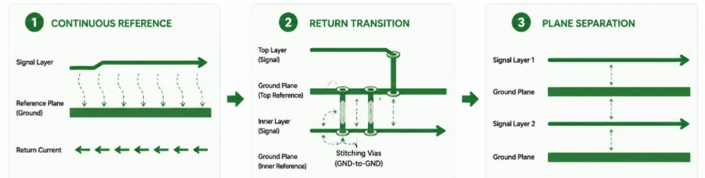
Laagtoewijzing en continuïteit van het retourpad
Elke hogesnelheidslijn heeft een doorlopende referentiegeleider nodig. Bij een gangbare, op signaalintegriteit gerichte tienlaagse opbouw verwijzen de buitenste seinen naar aangrenzende aardvlakken en worden bepaalde binnenste seinen tussen twee aardvlakken geplaatst. Deze opstelling is nuttig omdat de retourstroom dicht bij het sein kan blijven. Andere opbouwconfiguraties zijn ook mogelijk, maar de lay-outregels moeten dan wel overeenkomen met de daadwerkelijke referentiepunten.
Routeer niet over een referentiesplitsing.
Wanneer een printspoor een opening of een splitsing in het referentievlak kruist, buigt de retourstroom om de opening heen, waardoor het lusoppervlak groter wordt en de koppeling met andere structuren toeneemt. Het verplaatsen van het printspoor naar een laag met een continue referentie is meestal beter dan het achteraf toevoegen van een condensator. Als een voedingsvlak opzettelijk als hoogfrequente referentie wordt gebruikt, moet de verbinding met het relevante massadomein onderdeel zijn van het ontwerp.
Laagwijzigingen vereisen een terugkeerovergang.
Een signaalvia verplaatst de voorwaartse stroom tussen lagen; de retourstroom heeft ook een pad nodig tussen de oude en nieuwe referentiepunten. Massa-naar-massa-overgangen maken vaak gebruik van nabijgelegen verbindingsvias. Voeding-naar-massa-overgangen vereisen mogelijk een ontkoppelingsstructuur die zo geplaatst is dat de retourlus acceptabel klein is over het relevante spectrum. "Eén massavia binnen 50 mil" is een vuistregel, geen universele regel.
Aangrenzende signaallagen
Orthogonale routing kan de koppeling in de lengterichting tussen aangrenzende signaallagen verminderen, maar maakt een inherent slechte stapeling niet onschadelijk. Wanneer twee signaallagen tegenover elkaar liggen zonder vlak ertussen, beperk dan de overlap, vergroot de scheiding en reserveer het paar voor minder gevoelige netten. Voor kritieke seriële verbindingen is routing met vlakscheiding de voorkeur.
Differentiële paren: geometrie, scheefstand en overgangen
Een differentieel paar moet een consistente elektromagnetische omgeving behouden. De breedte, de afstand tussen de paren, de referentieafstand en het nabijgelegen koper moeten binnen de structuur blijven die gebruikt wordt voor de impedantieberekening. Korte vernauwingen bij de pads zijn mogelijk onvermijdelijk, maar deze moeten worden gemodelleerd of binnen een gevalideerde footprint worden gehouden.
Intra-pair skew is een elektrische grootheid.
Converteer de toegestane tijdsafwijking naar lengte met behulp van de werkelijke voortplantingsvertraging op de gerouteerde laag. Een paar dat van laag wisselt, kan een gelijke fysieke lengte hebben, maar een ongelijke vertraging als de twee sporen verschillende glaslagen bemonsteren, een andere via-geometrie gebruiken of verschillende referentieovergangen tegenkomen. Voor zeer snelle verbindingen is het beter om de vertraging en modusconversie te extraheren in plaats van alleen te vertrouwen op de hartlijnlengte van de PCB-tool.
Houd de twee overgangen symmetrisch.
Signaaloverdracht via pads, antipads, referentievias en breakout-punten moet waar mogelijk spiegelsymmetrisch zijn. Vermijd het plaatsen van een spoor dichter bij een vlak, montagegat of afschermingselement van een connector. Als polariteitsomkering is toegestaan door de interface, gebruik deze dan bewust in plaats van een lange kruising toe te voegen om de visuele oriëntatie te behouden.
Het matchen van paren is niet automatisch vereist.
Veel seriële ontvangers hebben een scheefstand tussen de lanes, waardoor het forceren van alle PCIe- of SerDes-paren tot dezelfde fysieke lengte onnodig verlies en omwegen kan veroorzaken. Volg de geldende eisen voor de scheefstand tussen lanes, maar geef prioriteit aan laag verlies, schone retourpaden en minimale overgangen. Scheefstand binnen een paar is doorgaans kritischer dan het matchen van niet-gerelateerde lanes met elkaar.
DDR5 en andere parallelle geheugeninterfaces
De beperkingen van DDR5 zijn afhankelijk van de controllerbehuizing, de DRAM-organisatie, de module- of downtopologie, de snelheidsklasse, het laden en de beëindiging. De juiste bron is de ontwerprichtlijn van de controller- en geheugenfabrikant, ondersteund door simulatiemodellen. Een algemene uitspraak zoals "DQ moet binnen +/- 5 mil overeenkomen" kan onnodig streng of onveilig zijn voor een specifiek platform.
Groepeer regels op functie
Definieer aparte groepen voor DQ/DMI ten opzichte van DQS, differentiële klok, commando/adres/besturing en eventuele modulespecifieke signalen. Gebruik waar mogelijk vertragingsbeperkingen in picoseconden, omdat de fysieke lengte op verschillende lagen anders wordt geconverteerd. De lay-outtool kan dan laagspecifieke vertraging toepassen in plaats van uit te gaan van één voortplantingsconstante.
Topologie is belangrijk
Commando-/adres- en kloksignalen kunnen in modulegebaseerde ontwerpen gebruikmaken van een fly-by-topologie, terwijl datasignalen bronsynchrone punt-naar-punt-verbindingen binnen een byte-lane zijn. Down-designs, geregistreerde modules en gebufferde modules introduceren andere laad- en routeringsmethoden. Kopieer geen DIMM-topologie naar een gesoldeerd ontwerp zonder de platformdocumentatie.
Referentie- en stroomintegriteit
De timing van het geheugen wordt beïnvloed door ruis in het referentievlak, de stroomverdeling en de lengte van de sporen. Houd de byte-lanes in een stabiele referentieomgeving, zorg voor een juiste VREF- en VDDQ-behandeling en vermijd het plaatsen van afstemmingsstructuren boven openingen in het vlak. Simuleer gelijktijdig schakel- en beëindigingsgedrag wanneer de platformmarge beperkt is.
PCIe- en snelle seriële verbindingen
Voor PCIe Gen5 en latere versies wordt de routekwaliteit voornamelijk bepaald door frequentieafhankelijk verlies, onderbrekingen in connectoren en via's, overspraak en modusconversie. Een lay-outregelset moet daarom meer omvatten dan alleen de beoogde impedantie.
| Regelcategorie | Praktische vereiste |
|---|---|
| Laagtoewijzing | Gebruik de laag en het materiaal die door het kanaalmodel worden weergegeven; vermijd het verwisselen van oppervlakken/binnenlagen die niet in het model zijn opgenomen. |
| Overgangsaantal | Minimaliseer laagwijzigingen en het openen van connectoren, maar ruil een schone referentie niet in voor een kortere route. |
| Via structuur | Gebruik het gevalideerde pad/antipad- en retour-via-patroon; definieer een back-drill- of blind-via-traject waar nodig. |
| Paar scheef | Pas de specificatie- of simulatielimiet in de tijd toe; zorg voor symmetrische uitbraak en afstemming. |
| Rijstrookafstand | Afgeleid van crosstalk-analyse en parallelle lengte, en niet zomaar een slogan die een veelvoud van de breedte is. |
| Testtoegang | Voeg geen onvoltooide stubs toe. Gebruik gevalideerde teststructuren of toegang via connectoren. |
| AC-koppeling | Volg de richtlijnen voor plaatsing van apparaten/vormfactoren en componentafmetingen; zorg voor een symmetrische omgeving voor het paar. |
PCIe 6.0 gebruikt PAM4 met 64 GT/s en dezelfde Nyquist-frequentie van 16 GHz als PCIe 5.0 NRZ, maar het is niet "hetzelfde kanaal met twee keer zoveel bits". De context van compliance, ruis en FEC verschilt. PCIe 7.0 met 128 GT/s verschuift de Nyquist-frequentie naar 32 GHz, waardoor transitie-extractie en correlatie met de productie veeleisender worden.
Overspraak, afstand en referentievlakruis
De vaak aangehaalde 3W- of 5W-regel is een geometrische vuistregel. Overspraak is ook afhankelijk van de diëlektrische dikte, de lengte van de parallelle laag, de stijgtijd van de stoorbron, de referentiestructuur en of de lijnen aan de rand of loodrecht op elkaar gekoppeld zijn. Op een dunne diëlektrische laag kan een kleinere afstand al voldoende zijn; op aangrenzende, niet-gerefereerde signaallagen kan een grote afstand nog steeds ontoereikend zijn.
Stel een overspraakdoel in dat geschikt is voor de interface en gebruik extractie of een gevalideerde geometrietabel om dat doel om te zetten in afstand. Houd rekening met de volledige lengte van het slachtoffer en gelijktijdige aanvallers. Klok-, stroboscoop- en single-ended netwerken met hoge zwaaifrequentie verdienen mogelijk meer isolatie dan ongerelateerde, langzame controlemechanismen.
Ruis in het vlak kan via de referentiestructuur doordringen, zelfs bij ruime afstand tussen de sporen. Houd schakelcircuits met hoge stroomsterkte compact, gebruik geschikte vlakparen en ontkoppeling, en voorkom dat gevoelige sporen gefragmenteerde voedingseilanden als referentie gebruiken. Overspraak en voedingsintegriteit moeten samen worden beoordeeld op processoren met een hoge dichtheid en acceleratorboards.

Afbeelding 2. Routing en retourpadlay-out van een 10-laags printplaat.
Lengte-afstemming zonder een nieuwe discontinuïteit te creëren
Meanders zorgen voor vertraging, maar dicht bij elkaar gelegen segmenten koppelen aan elkaar en leveren minder vertraging op dan hun middellijnlengte doet vermoeden. Ze verhogen echter ook het verlies en creëren lokale impedantievariaties. Gebruik de grootst mogelijke afstand tussen aangrenzende afstemsegmenten, minimaliseer het aantal windingen en verdeel de afstemming zo dat deze de doorbraaksignalen of de referentiecontinuïteit niet verstoort.
Er is geen universele regel die voorschrijft dat afstemming dicht bij de bron of dicht bij de ontvanger moet plaatsvinden. De plaatsing hangt af van de topologie en het doel van de aanpassing. Bij een bronsynchrone bus stemt u af binnen de gedefinieerde groep en behoudt u de topologie. Bij een differentieel paar corrigeert u de scheefstand met een compacte, symmetrische constructie die geen lang ongekoppeld gedeelte creëert.
Afgeronde hoeken zijn niet per se vereist, en een enkele bocht van 90 graden resulteert niet in een reflectie van 15% in elke geometrie. Gebruik bochten van 45 graden of gebogen routing voor een betere produceerbaarheid, paarsymmetrie en consistente afstand, maar concentreer de engineeringinspanning op grotere discontinuïteiten zoals pads, via's, connectoren en onderbrekingen in het referentievlak.
BGA-ontsnapping, via's en maakbaarheid
De BGA-pitch alleen bepaalt niet of HDI nodig is. Paddiameter, soldeermaskerstrategie, aantal rijen, pinmapping, beschikbare routinglagen en ontsnappingsrichting spelen allemaal een rol. Sommige componenten met een pitch van 0.5 mm kunnen gebruikmaken van een zorgvuldig ontworpen through-via of een beperkte blind-via-aanpak; andere vereisen via-in-pad en meerdere opbouwlagen. Bekijk de werkelijke fanout van het pakket in plaats van alleen een pitchtabel te gebruiken.
Bij de via-in-pad moet worden aangegeven of de via met koper is gevuld, met hars is gevuld en afgedekt, of via een ander gekwalificeerd proces is vervaardigd. Voor gestapelde microvias moeten de opbouwvolgorde en het betrouwbaarheidsplan worden overeengekomen. HDI-gids Dit omvat de selectie van de structuur; de lay-out moet nog steeds voorzien in vanggebieden, anti-pads en uitsluitingszones die compatibel zijn met de registratiemogelijkheden van de leverancier.
De ontsnappingsroutering moet ook de referentiecontinuïteit behouden. Dichte antipad-velden kunnen te veel koper onder een behuizing verwijderen, dus de stroom- en massa-uitgang moet als een elektromagnetische structuur worden beschouwd. Het toevoegen van meer massa-vias is niet altijd gunstig als dit leidt tot te grote holtes of de routing belemmert.
Beoordeling van de prefabricageroute
| Beoordelingsartikel | Vrijgavevraag |
|---|---|
| Stackup-revisie | Verwijzen alle regels en simulaties naar de exacte stackup die wordt genoemd? |
| Gecontroleerde structuren | Zijn de toewijzingen van breedte, afstand, masker en laag gekoppeld aan de impedantietabel? |
| Retourpaden | Heeft elke kritieke route en elke wijziging in de laag een ononderbroken retourpad? |
| Timing | Worden de limieten overgenomen van het daadwerkelijke apparaat/de topologie, bij voorkeur in de tijd in plaats van gekopieerde mil-waarden? |
| Verlies en overgangen | Worden kritieke routes geëxtraheerd met het geselecteerde materiaal, koper en via-/connectormodellen? |
| Overspraak | Zijn de afstandsregels gekoppeld aan een doel en een parallelle lengte? |
| BGA-ontsnapping | Is de via-constructie produceerbaar en geschikt voor de gekozen constructie? |
| Koperbalans | Voldoen de routing en het gieten aan de eisen met betrekking tot kromtrekking en beplating van de stapelconstructie? |
| DFM-autoriteit | Is het duidelijk welke wijzigingen de fabrikant zonder toestemming aan het kunstwerk mag aanbrengen? |
Een DFM-review mag elektrische beperkingen niet stilletjes herschrijven. Wanneer CAM een wijziging voorstelt in breedte, pad, antipad of stackup, moet deze wijziging worden gecontroleerd aan de hand van het impedantie- of kanaalmodel en worden gedocumenteerd. Dien de definitieve lay-out samen met de fabricagetekening en netlijst in via de DFM-beoordelingsproces.
Connectorlanceringen, printplaatgrenzen en teststructuren
Connectoren vertonen vaak grotere onderbrekingen dan gewone bochten. Bekijk het signaalpad, antipad, het patroon van de massapinnen, de uitsparingen in de vlakken en de overgang naar het gerouteerde paar als één geheel. Referentie-footprints van de fabrikant zijn een uitgangspunt, geen garantie, omdat de dikte van de printplaat, de laagindeling en de fabricageafmetingen kunnen verschillen. Gebruik voor de snelste connectoren het model van de fabrikant en extraheer de lokale PCB-aansluiting.
Vermijd abrupte beëindiging van het referentievlak aan de randen van de printplaat onder een gevoelige route. Contacten aan de printplaatrand, coax-uitgangen en mezzanine-connectoren vereisen mogelijk aardingsvorming, via-afschermingen of lokale laagovergangen die specifiek zijn voor de interface. Houd mechanische uitsluitingen, platingstrips en afbreekbare lipjes buiten het elektrische referentiegebied, tenzij ze in het model zijn opgenomen.
Ontwerp testtoegang zonder stubs te creëren.
Standaard testpunten en vertakte testpunten kunnen extra capaciteit of een niet-afgesloten verbinding toevoegen. Gebruik een gevalideerde testcoupon, connectortoegang, een verwijderbare componentoptie of een pad dat is geïntegreerd in het hoofdtransmissiepad. Stem de in-circuit testvereisten af op de signaalintegriteit voordat de lay-out is voltooid; het verwijderen van een testtak na kwalificatie kan ook het kanaal wijzigen.
Documenteer opzettelijke uitzonderingen
Bij dichte lay-outs is soms een lokale breedteaanpassing, een referentieovergang of een schending van de afstandseisen nodig. Leg de locatie, de reden en de goedkeuring van de simulatie of leverancier vast. Een gedocumenteerde uitzondering is veiliger dan de regel in het algemeen te versoepelen of te vertrouwen op een toekomstige DFM-ingenieur om de ontwerpintentie af te leiden.
Klok-, analoge en stroomrouteringsgrenzen
Niet elk belangrijk netwerk is een differentiële seriële verbinding. Referentieklokken, resetsignalen, analoge sensorpaden en schakelende voedingsknooppunten kunnen interferentie veroorzaken of ontvangen. Classificeer netwerken op basis van flankfrequentie, ruisgevoeligheid en stroomlus in plaats van alleen op basis van de nominale frequentie. Een laagfrequente klok met een snelle flank kan meer aandacht vereisen dan een sinusgolf met een hogere frequentie.
Referentieklokken
Leid referentieklokken over een continu vlak, vermijd onnodige teststubs en isoleer ze van schakelknooppunten. De vereiste topologie – punt-na-punt, fanoutbuffer of een andere distributiemethode – is afgeleid van de specificaties van de klokbron en -ontvanger. Een stertopologie of daisy chain is niet universeel correct. Simuleer het laden en beëindigen van meerdere ontvangers.
Analoge en converterinterfaces
Houd kleine analoge lussen compact en scheid ze van agressieve digitale retourstromen. Het splitsen van het massavlak is niet automatisch voordelig; een continu vlak met een doordachte plaatsing zorgt vaak voor een lagere retourimpedantie. Als analoge en digitale domeinen op een gecontroleerd punt moeten samenkomen, zorg er dan voor dat signalen de resulterende opening niet overbruggen en dat de verbindingsstrategie overeenkomt met de richtlijnen van de converterfabrikant.
Schakelende stroomgebieden
De schakelknoop, de gate-aansturingslus en de stroompaden met hoge di/dt-waarden verdienen fysieke uitsluitingszones. Leid geen snelle stroomparen onder inductoren, transformatoren of koperen schakelknopen door. Vlakke holtes en uitsluitingszones moeten worden meegenomen in de beoordeling van het retourpad. De stroomvoerende breedte en thermische prestaties moeten worden geëvalueerd met behulp van IPC-2152-methoden of gevalideerde simulaties, in plaats van een universeel stroomdichtheidsgetal.
Leg deze gebieden vast in de lay-outbeperkingen, zodat DFM-kopertoevoegingen, -diefstal of paneelfuncties niet onbedoeld in een gevoelig gebied terechtkomen.
Goedkeuring routeringsregel
De uiteindelijke routingcontrole moet de lay-out vergelijken met de vrijgegeven stackup en apparaatspecifieke beperkingen, in plaats van met een algemene checklist van mil-waarden. Kritieke groepen moeten worden gecontroleerd met behulp van geëxtraheerde vertragings-, verlies- en overgangsmodellen, waar deze effecten van belang zijn.
- Controleer of elke kritieke route over een continue referentie blijft en of laagovergangen een retourstroompad bieden.
- Controleer de differentiële geometrie via vernauwingen, pads, via's, connectoren en teststructuren - niet alleen op rechte sporen.
- Pas de geheugentiming aan op basis van byte-lane, commando-/adresgroep en topologie met behulp van de controller- en geheugendocumentatie.
- Beperk meanders en parallellisme op basis van vertragings- en overspraakanalyse in plaats van een universele afstandsvermenigvuldiger.
- Controleer of de BGA-fanout, ringvormige aansluitingen, antipads en via-afstanden overeenkomen met de door de leverancier goedgekeurde specificaties.
- Lever het definitieve ontwerp, de netlijst, de boor-/routeringsgegevens, de herziening van de opbouw, de impedantietabel en de tekening met gecontroleerde diepte aan als één revisiegecontroleerd pakket.
De lay-outregels moeten het elektrische doel en de bron ervan duidelijk aangeven. Dit maakt uitzonderingen beoordeelbaar en voorkomt dat een wijziging in het fabricageproces de ingestelde routingbeperkingen ongemerkt ongeldig maakt.
Het beheren van routeringsuitzonderingen
Bij dichte lay-outs zijn uitzonderingen op de voorkeursregels onvermijdelijk nodig. Het doel is niet om elke vernauwing, laagovergang of lokale afstandverkleining te verbieden; het is om te bepalen welke uitzonderingen elektrisch significant zijn en deze te beoordelen met het juiste model.
| uitzondering | Beoordelingsmethode | Bewijs vrijgeven |
|---|---|---|
| Korte BGA hals omlaag | Modelleer de lokale impedantie en lengte; bevestig de ets- en maskermogelijkheden. | Maximale lengte, breedte/afstand en getroffen lagen in de regelset. |
| Referentievlakovergang | Controleer de retourstroomlus en het verbindings-/ontkoppelingspad. | Gevalideerd via-veldpatroon of gedocumenteerde lokale lay-out. |
| Verkleinde afstand tussen paren | Extraheer de overspraak om de werkelijke parallelle lengte en de activiteit van de agressor te bepalen. | Toegestane duur en locatie, geen algemene vrijstelling. |
| Extra meander | Controleer het uitstelvoordeel, de zelfkoppeling en het extra verlies. | Minimale windingafstand en maximale stemdichtheid. |
| Onvermijdelijk via stub | Modelleer resonantie en vergelijk deze met alternatieven zoals achterboren of blindboren. | Goedgekeurde laagdikte en vereiste reststuklengte. |
Uitzonderingen moeten worden gekoppeld aan netten, regio's of klassen en worden opgeslagen in het ontwerpbeoordelingsdossier. Een algemene mondelinge goedkeuring zoals "afstand is acceptabel" kan niet worden herhaald tijdens een ECO of leveranciersoverdracht. Hetzelfde principe geldt voor referentielay-outs van apparaatfabrikanten: behoud de elektrische intentie, maar valideer de afmetingen opnieuw aan de hand van de vrijgegeven printplaatopbouw.
Het beoordelingsverslag moet ook de extractie- of simulatieversie vermelden die is gebruikt voor kritieke uitzonderingen. Wanneer een ECO een component verplaatst, een laag wijzigt of de voetafdruk van een connector aanpast, kan de betreffende uitzondering opnieuw worden beoordeeld in plaats van een goedkeuring over te nemen die niet langer overeenkomt met de geometrie.

aanbevolen berichten

Taconic RF-35 PCB-productieservice — van prototype tot serieproductie
Afbeelding 1. Taconic RF-35 printplaat. De Taconic RF-35 is het werkpaard...

Isola Astra MT77 PCB-productie
Afbeelding 1. Fabricage van de printplaat Isola Astra MT77...

Op maat gemaakte Rogers RO4835 printplaatfabricage en -assemblage
Afbeelding 1. Rogers RO4835 printplaat. De Rogers RO4835 printplaat is een...

Nelco N4000-13 PCB-materiaal- en fabricagehandleiding | Highleap Electronics
Afbeelding 1. Nelco N4000-13 printplaat. De Nelco N4000-13 printplaat is een...
Hoe u een offerte voor PCB's kunt krijgen
Wij voeren graag een DFM/DFA-analyse voor u uit en sturen u vervolgens een rapport. U kunt uw bestanden veilig uploaden via onze website. Om u een offerte te kunnen geven, hebben we de volgende informatie nodig:
-
- Gerber, ODB++ of .pcb, spec.
- BOM-lijst als u assemblage nodig heeft
- Aantal
- Draaitijd
Voor PCBA-diensten verzoeken wij u uw BOM (Bill of Materials) en eventuele specifieke assemblage-instructies te verstrekken. Wij bieden ook DFM/DFA-analyses aan om uw ontwerpen te optimaliseren voor maakbaarheid en assemblage, wat een soepel productieproces garandeert.