Flex PCB Assembly
Push Boundaries of Innovation – Flex PCB Assembly Solutions by Highleap
Flex PCB Assembly
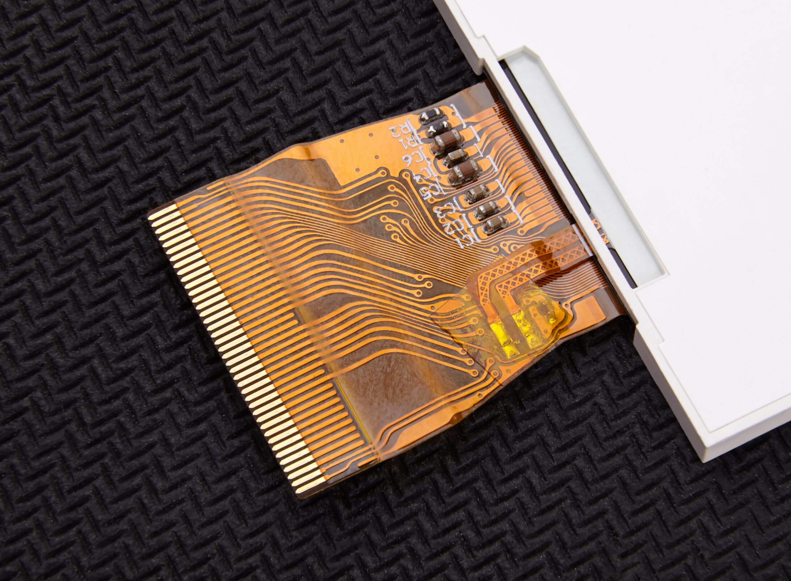
Flex printed circuits (FPCs) require specialized assembly and soldering processes that differ from rigid PCBs due to their flexible nature. Without a rigid carrier fixture, FPCs cannot be securely held in place for basic surface mount technology (SMT) processes like solder paste printing, component placement, and reflow soldering.
Their lack of rigidity needs custom carrier boards for stability and conveyance during manufacturing. Proper fixturing and tailored process parameters are critical for robust solder joints, accurate placement, and reliable interconnections on flex PCB assembly. The flexing nature of FPCs adds complexity to assembly that must be addressed through optimized fixtures, settings, and procedures.
The customized fixtures, optimized equipment settings, stringent process diligence, and thorough inspection regime enable a high-yield, repeatable flex circuit SMT assembly process. This results in robust and reliable products that leverage the benefits of flex circuitry.
Highleap offers a comprehensive range of services for flex PCB manufacturing and flex PCB assembly, including 1-12 layer flex PCB, full/partial BOM list procurement, and final flex PCB testing. Simply send us your flex PCB file and BOM list to receive a quick quote for both flex PCB and flex PCB assembly.

Flex PCB Assembly Process
FPC Pretreatment
Prior to SMT assembly, the flex circuit requires baking at 80-100°C for 4-8 hours to remove absorbed moisture and prevent vaporization defects during reflow.
Carrier Fixture Preparation
The flex circuit is fixed to a carrier fixture for stability during assembly. Fixtures use precision pins or holes to align the flex circuit. Materials like silicone, magnetic steel, and synthetic stone provide optimal thermal and mechanical properties while minimizing warpage.
FPC Positioning
The flex circuit is carefully positioned on the carrier fixture and fixed with high-temperature tape on all sides. This prevents shifting or warpage during processing. Spring-loaded pins allow pressing during printing. Minimal time between positioning and soldering is ideal. Operators wear finger cots to avoid contaminating the flex circuit. The fixture is cleaned before reuse.
Solder Paste Printing
Solder paste is precisely printed on SMT pads through a matching stencil. Automatic inspection verifies alignment and paste release. Adhesive carriers may be used to aid thin flex circuit stability.
SMT Component Placement
Components are accurately placed on solder paste using automated pick-and-place machinery. Special carriers maintain stability. Optical and mechanical checks verify placement accuracy.
Reflow Soldering
The assembly enters a reflow oven to attach components. The fixture prevents flex circuit warpage under heat. Precise thermal profiles ensure quality solder joints without overheating.
Inspection and Testing
Automated optical, X-ray, and electrical testing validate solder connections, placement, board integrity and functionality. Failed boards are reworked or scrapped.
Fixture Removal and Final Inspection
Fixtures are carefully detached prior to final visual inspection and quality control. Approved assemblies are packaged for delivery.
Flex PCB Assembly Characteristics
Flex PCB Assemblies (PCBAs) provide unique benefits but also pose distinct manufacturing challenges compared to rigid PCBAs due to the flexible, dynamic nature of the base material. Key Flex PCB Assembly characteristics include
- Materials – The thin, flexible substrates consist of polyimide, polyester, or other polymer films with very low rigidity. They are combined with flexible conductive traces of copper or aluminum.
- Layer Stackup – Flex circuits typically have 1-2 conductive layers, although some complex designs may have up to 6 layers. The simpler construction aids flexibility.
- Geometries – Tight bend radii, dynamic flexing regions, and three-dimensional shapes are enabled by the flexible materials.
- Interconnections – Layer-to-layer connections rely on conductive adhesives or flexible solders rather than plated through holes. Flat flex cables can terminate in connectors.
- Assembly Processes – Carrier boards provide rigidity for SMT assembly steps like screen printing, pick-and-place, and reflow soldering. Dedicated flex component packages are used.
- Inspection – Optical and X-ray methods are adapted for the low-contrast flexible materials. Electrical testing requires fixturing strategies.
- Reliability – Dynamic flexing leads to fatigue over lifetimes. Adhesives and solders must withstand flexing stresses. Hermetic seals are challenging.
The combination of delicate materials and dynamic flexing introduces difficulties in Flex PCB Assembly, such as maintaining registration accuracy, achieving robust bonds, preventing warpage, mitigating fatigue, and inspecting low-contrast features. However, proper design strategies and advanced assembly processes can overcome these challenges to fully realize the advantages of flex circuits. Revolutionize your product with flex PCBs built to last by Highleap’s advanced Flex PCB Assembly processes.
Key Equipments in Flex PCB Assembly
Contact us now to discuss how Highleap’s engineering methods and expertise in flexible PCBs can bring your complex flexible circuit designs to production with unparalleled quality, reliability, and yield. Below are specific details on key equipment in flex PCB assembly:
1. Solder Paste Printer
Solder paste printers accurately deposit solder paste on SMT pads through a stencil. For flex circuits, printers must handle thin, delicate materials and often utilize carrier boards for stability. Optical alignment and inspection ensures proper registration.
2. Pick-and-Place Machine
Also known as placers or surface mount devices (SMD) machines, these rapidly and precisely place components onto solder paste deposits. Flexible feeders and optimized placement heads are required for thin flex circuits.
3. Reflow Oven
Reflow ovens use precisely controlled heat profiles to form solder joints between components and pads. Forced convection and/or infrared heating is optimized for flex circuit materials to prevent warpage.
4. Automated Optical Inspection (AOI)
AOI systems use cameras and software to automatically detect assembly defects like missing solder, misplaced components, etc. Flexible board inspection requires high-resolution cameras and advanced algorithms.
5. Component Trim and Form
These machines cut, bend, and form odd-shaped component pins to enable hand soldering or insertion into PCBs.
6. Wave Soldering
A wave solder machine forms a molten solder wave to simultaneously attach leaded components and connectors to a PCB. Flex boards may require carrier boards and edge masking.
7. Hand Soldering Station
Operators use soldering irons, hot air tools, and microscope inspection for manual soldering, repairs, and rework. Fume extraction is critical.
8. Cleaning System
Aqueous, semi-aqueous, or solvent cleaning removes flux residues from PCBA boards after soldering. Flex boards require optimized contact methods.
9. In-Circuit Test (ICT)
ICT fixtures contact test points on an assembled PCB to validate solder joints, component placement, and electrical connections using a bed-of-nails.
10. Functional Test (FCT)
FCT applies simulated electrical inputs to a functioning board and validates the outputs match specifications and design functionality.
11. Environmental Stress Screening
Burn-in rigs subject boards to thermal cycling and vibration over time to precipitate early product failures before shipment.
Soldering Requirements for Flex PCB Assembly
Joint Geometry
Ensure proper pin height for through-hole components and flat positioning for SMDs with smooth fillets. Avoid insufficient solder coverage, balling, or solder on pads.
Fillet Shape
The solder fillet shape should be conical, smoothly covering the entire pad area to ensure proper soldering integrity.
Wetting and Adhesion
The solder joints must exhibit complete wetting of pads and pins, with no occurrence of dry or cracked joints, ensuring robust adhesion and reliable electrical connections.
Joint Height
Solder joint height should be at least 1mm for single-sided boards and 0.5mm for double-sided boards, with good wetting underneath terminations.
Joint Finish
The solder joint surface should be smooth, shiny and free of defects like flux residue, exposed copper, spikes and pits.
Component Placement
Through-hole components and pin headers should be mounted flush, aligned within specifications and straight/level. Components should float no more than 0.5mm off the board.
Highleap’s flex PCB assembly Advantages

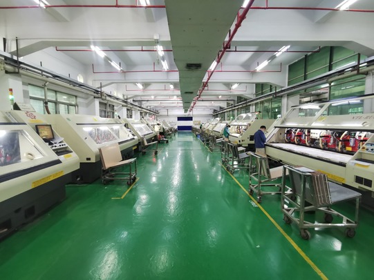
At Highleap, our commitment to excellence in Flex PCB Assembly sets us apart from the competition. Equipped with cutting-edge facilities and a highly skilled team of engineers and technicians, we are dedicated to providing the highest standard of quality throughout the entire assembly process. With our expertise in Flex PCB Assembly, we deliver reliable, high-performance solutions that meet your specific requirements and exceed your expectations.
Key Advantages of Highleap’s Flexible Circuit Assembly Services:
- Engineering Excellence
- Precision Manufacturing
- Superior Material Selection
- Stringent Quality Control
- Scalable Solutions
- Cost Efficiency
- Confidentiality and Intellectual Property Protection
Experience and reputatio
Select a FPC assembler with an excellent industry reputation built over many years of producing top-notch flex circuits.
Certifications
Choose a flex PCB producer certified to ISO 9001, showing commitment to quality and compliance to standards.
Quality control
Select a manufacturer with a robust quality control process and advanced testing equipment to detect defects.
Customer service
Although cost is key, find a FPC maker offering competitive pricing balanced with quality, reliability and performance.
Material selection
Ensure the manufacturer uses high-quality materials suitable for your application and provides guidance on material selection.
Manufacturing capabilities
Ensure the manufacturer can produce various Flex PCB types, sizes, and shapes as per your requirements.
