Rigid-Flex PCBs
We provide manufacturing and assembly services for all kinds of rigid-flex PCBs.
What are Rigid Flex PCBs?
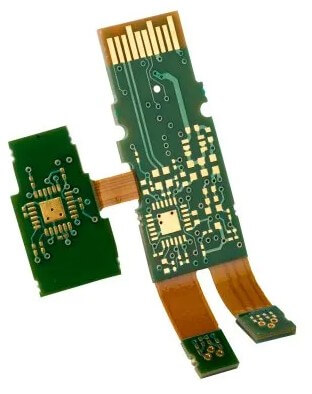
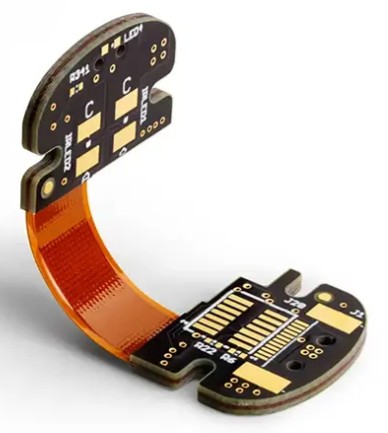
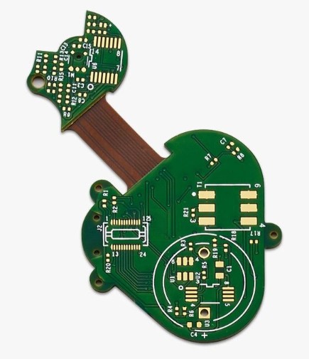
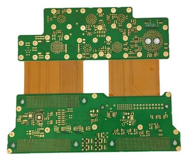
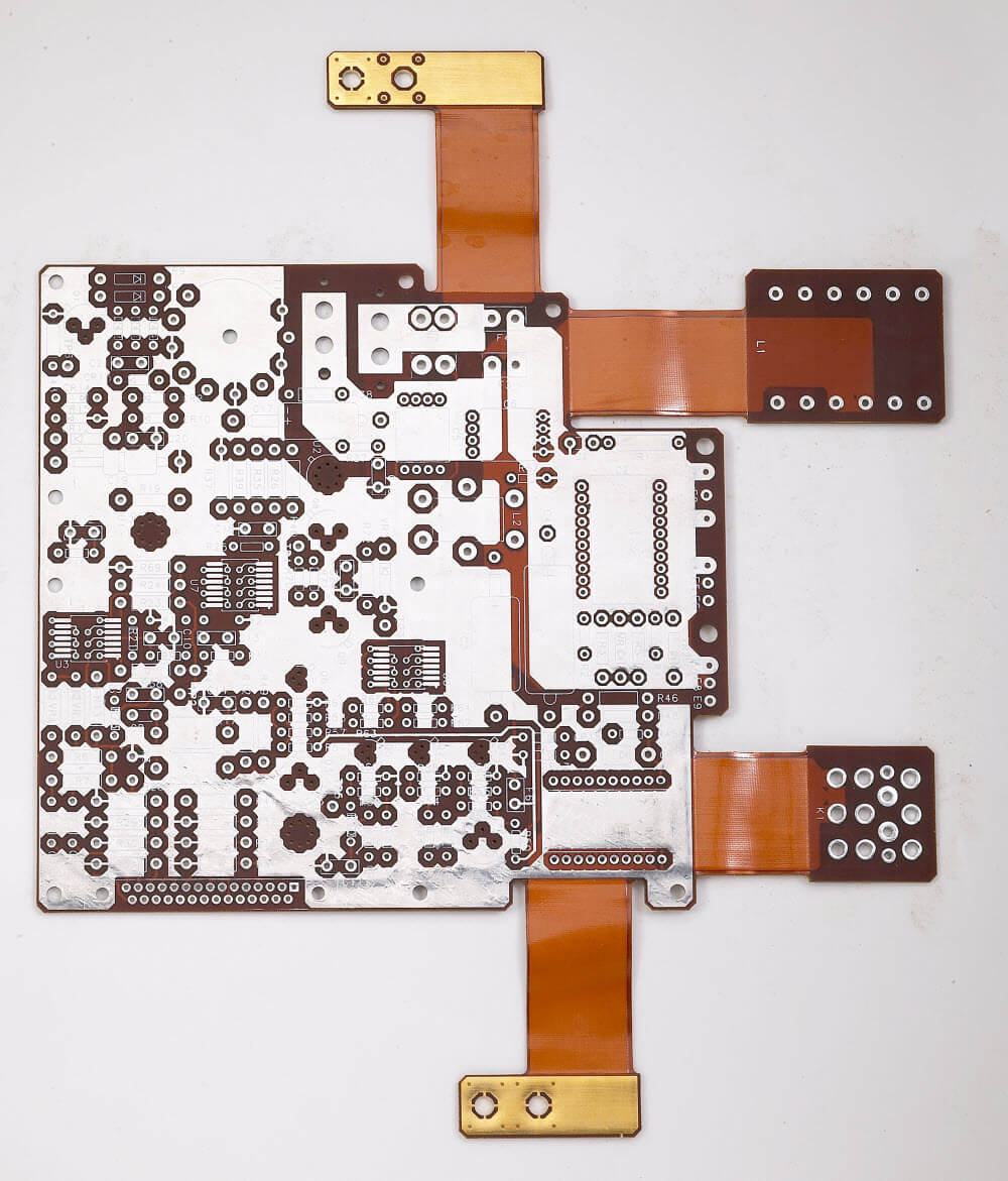
Multilayer rigid-flex boards are a type of printed circuit board that combines both rigid and flexible board technologies for specific applications. These types of PCBs typically consist of multiple layers of flexible circuit substrates that are attached to at least one rigid board, either internally or externally, depending on the design requirements.
The flexible substrates in multilayer rigid-flex PCBs are designed to remain in a constant flex state and are formed into a flexed curve during installation or manufacturing. However, designing multilayer rigid-flex PCBs is more challenging than designing rigid boards since it requires designing in a 3D space, which provides more spatial efficiency.
With the ability to have a three-dimensional design, designers can roll, fold, and twist the substrates of the flexible board to achieve the desired shape. This allows for greater design flexibility and the ability to create more complex and compact PCBs.
We specialize in the manufacturing of multilayer rigid-flex PCBs, providing our customers with high-quality, reliable products that meet their specific needs. Our experienced team of engineers and technicians is dedicated to delivering the highest level of service and quality to ensure that our customers’ applications are successful.
The Benefits of Rigid-Flex PCB
As a leading PCB manufacturer, Highleap specializes in creating compact, customized rigid-flex printed circuit boards that maximize functionality.
Below are some of the major benefits of the Semi-rigid PCB:
- It is lightweight and compact due to its flexible nature. This reduces the overall size and packing volume.
- Flexibility – Rigid flex boards can adapt to the shape of existing devices instead of designing the device to fit the PCB.
- They can fit into small and confined spaces easily due to their flexibile design. This enables miniaturization of products.
- They are reliable as there are no solder joints, connectors, or contact crimps. This ensures integrity and reliability.
- They have good thermal stability due to the use of polyimide, which can withstand harsh temperatures. This makes them suitable for defense and military applications.
- Reduced circuit failure – The combination of rigid and flexible circuitry reduces the number of interconnections, lowering failure rates.
- Cost-effective – Rigid flex PCBs require less material so they are cheaper to procure and manufacture.
In summary, semi-rigid PCBs offer benefits like compactness, flexibility, reliability, thermal stability, and cost savings – all of which make them useful for many applications.
Contact Highleap today for a consultation on your next rigid-flex PCB design. Our team of rigid-flex experts will work with you to determine the optimal combination of rigid and flexible layers to meet your size, performance and budget requirements.
Flex PCBs VS Rigid-Flex PCBs?
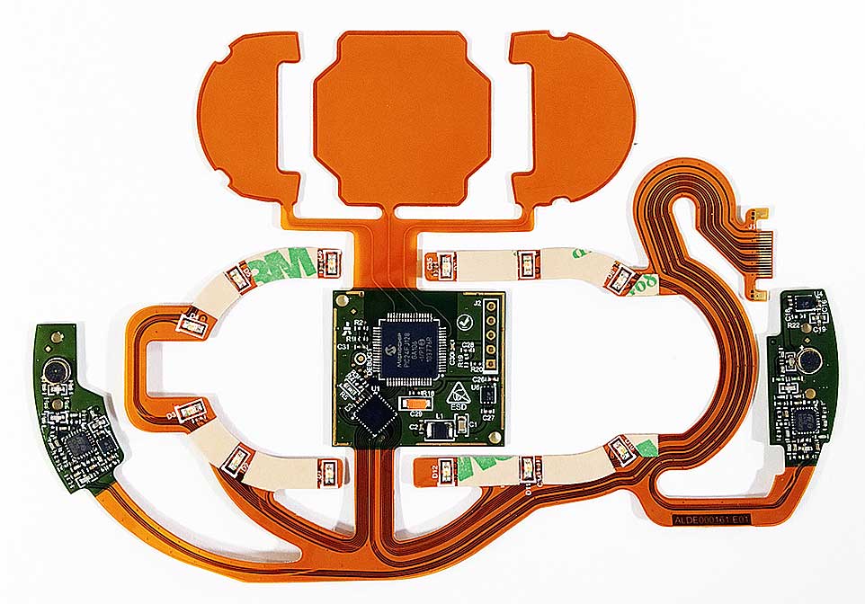
The rigid-flex printed circuit board combines the best aspects of flex circuits and rigid PCBs. A rigid-flex PCB consists of both rigid and flexible materials, with flexible layers sandwiched between rigid layers connected by plated through-holes.
A flex printed circuit board is made entirely of flexible materials, typically polyimide or polyester, and can have single, double, or multilayer constructions. Flex circuits alone offer design flexibility but may lack durability for demanding applications.
Standard rigid PCBs tend to be heavier and require more space. However, integrating flexible circuits into a rigid-flex design offers: Reduced weight, a more compact footprint, increased design flexibility.
Materials Selection in Rigid-Flex PCBs
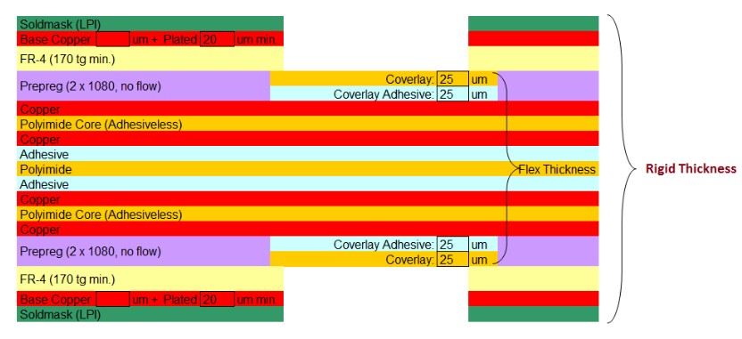
The rigid sections of the PCB typically use conventional FR-4 substrates or other glass-reinforced epoxy laminates. These provide the necessary stiffness and dimensional stability for the rigid regions which often contain surface mount components. The coefficient of thermal expansion and thickness are selected to match the target application.

The bonding layer requires high performance adhesives. Acrylic, epoxy, phenolic or polyimide adhesive films typically used. Thermoplastic adhesives provide best results. Needs robust adhesion,high strength, resistance to heat, chemicals and environment. Incorporating electrostatic discharge (ESD) films within adhesive stackup crucial for preventing static charge damage. ESD films provide conductive pathway for grounding.Compatible adhesive and ESD films vital for ESD protection in multilayer PCBs.
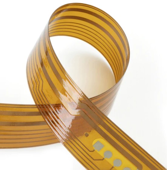
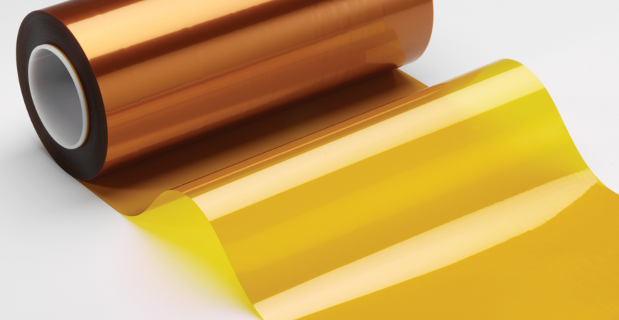
The flexible layers require specially engineered polymer films capable of dynamic flexing and bending. Polyimide films such as DuPont’s Kapton are commonly used due to their excellent electrical properties and very high bend ratios. Other flexible polymer options include polyester (PET), polyethylene naphthalate (PEN), or liquid crystal polymer (LCP) films. The flex layers are thinner for increased pliability.
Careful selection of the rigid, flexible, and adhesive materials enables reliable construction of complex multilayer rigid-flex PCBs. The combination of properties allows both dynamic flexing and structural support while maintaining electrical performance and withstanding thermal cycling stresses.
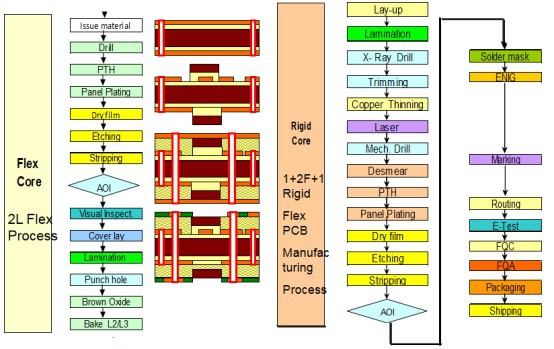

Guidelines for Rigid-Flex PCB Design
During the manufacturing process of a rigid-flex PCB, the design and layout stage are crucial. Here are some important elements to consider:
Guidelines for Rigid-Flex PCB Design:
Stick to the laid-down design rules when making corners and bends, ensuring they are not sharp.
When changing the traces’ width, make sure to do it gradually to avoid creating weak spots. Using at least two flex layers can help reduce costs and increase the flexibility of the circuit.
Rigid-Flex Circuit Layout Guidelines:
Ensure that the calculator for trace width delivers accurate results for trace spacing and width between the flexible parts. Complete the solder pads in either rounded or teardrop styles, and apply the same to tracks.
Make sure that both the soldering surfaces and annular rings are large, and use stiffeners to achieve the desired thickness.
Apply coverlays on flexible boards to provide insulation and protection on the outer surface of the conductors. When soldering, the coverlay plays a significant role in restraining and holding the pads.
Ensure that the pads feature anchoring spurs to prevent separation between the copper and the material during the assembly process. Filleting the pads reduces stress points and the chances of breakage when flexing.
Metalize plated vias to connect the flexible circuit and conductive layers. Blind vias should connect the inner layer, and buried vias should connect all internal layers while ignoring the outer layers. Using different via types can augment any space present in the circuit and allow for additional component pads and trace routing.
Avoid using vias when working with the flex substrate of the rigid-flex PCB. If necessary, place them in areas that will not be bent.
Emphasize accuracy when calculating the bending radius of the rigid-flex circuit to prevent breakages.
We follow strict guidelines and standards during the design and layout stage to ensure that our rigid-flex PCBs are of the highest quality and meet our customers’ specific needs.
Highleap’s Capabilities about Rigid-Flex PCB
In terms of surface finishes, we provide various choices to enhance the solderability, corrosion resistance, and conductivity of the circuit boards. Common surface finish options as below:
- HASL (vertical or horizontal)
- Lead-free HASL
- OSP (Shikoku F2)
- OSP (Entek)
- ENIG
- Immersion silver
- Immersion white tin
- Tin nickel
- Electrolytic soft gold
- Electrolytic hard gold
- Selective gold
These surface finish methods can be selected and optimized based on your specific needs and application.
Our design expertise, manufacturing capabilities and wide range of options are ready to optimize your board for function, reliability and cost efficiency.
For other technologies, requestments and more detailed information, please feel free to contact us.
Specifications
Min Core thickness
Max Finished Copper Weight (I/L)
Max Finished Copper thickness
Smallest Mechanical Drill Diameter
Smallest Laser Drill Diameter
Min Finished Hole Size
Max through Hole Aspect Ratio
Max Blind Via Aspect Ratio
Min Trace and Space
Min Pad Size for Test
Application of Rigid-Flex PCB
Consumer Electronics
Smart toys
GPS systems
Wireless routers
Digital cameras
Wearable equipment
Drone equipment
LED lighting systems
Cellphone and computer
Industrial and Medical Devices
Medical equipment
Aerospace systems
Automotive controls
Robotics systems
Power equipment
Satellite communication
Audio and video equipment
Industrial control systems
IoT and Smart Home Electronics
Smart locks
Smart home appliances
Smart thermostats
Energy management
Home entertainment equipment
Access control equipment
Security and surveillance equipment
Environmental monitoring systems
High Quality and Fast Delivery
Highleap has industry-leading technology and facilities, by leveraging the complementary benefits of rigid circuitry for stability and flexible circuitry for shape, we can provide: High-density solutions, Compact form factors, Design flexibility, Fast turnaround.
Contact us now. Our rigid-flex experts are ready to create a customized solution that meets your size, performance and budget requirements.

