
Back to blog
Guide to PCB LED Light Circuit Design by Highleap Electronic

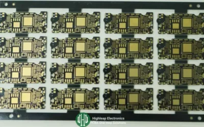
Batch copper-based PCB LED circuit boards
LED lighting is now the preferred choice for a multitude of applications, including automotive, residential, and outdoor lighting due to its high output lumens, efficiency, and longevity. Central to the functionality of LED lighting is the Printed Circuit Board (PCB), which supports and connects the LEDs. This comprehensive guide will delve into the intricacies of PCB LED light circuit design, highlighting its benefits, challenges, applications, and best practices for ensuring optimal performance.
Understanding PCB LED Light Circuit Design
PCB LED light circuit design involves the integration of LEDs onto a PCB to create a compact and efficient lighting solution. The core component, the LED, is a semiconductor diode that emits light when an electrical current passes through it. This chip is typically mounted on a ceramic base attached to a thermal heat sink to manage the significant heat output that LEDs generate. Metal core PCBs, particularly those made from aluminum, are commonly used in LED applications due to their excellent heat dissipation properties.
Why Use PCB LED Light Circuit Design?
PCB LED light systems rely on PCBs as their foundation and offer several advantages.
-
- Compact Size: The small size of LEDs makes them suitable for various applications, including computers, automobiles, smartphones, floodlights, and traffic lights.
- Lower Power Consumption: LED lighting is highly energy-efficient, reducing power consumption by approximately 80% compared to traditional lighting sources.
- Longer Lifespan: LEDs have a lifespan that is significantly longer than traditional light sources, lasting up to 25 times longer.
- Mercury-Free: Unlike traditional bulbs, LEDs do not contain mercury, making them environmentally friendly and easier to dispose of.
- Efficiency: LEDs generate less heat compared to incandescent lights, with about 90% of energy used for lighting rather than heating.
Despite these advantages, designing PCB LED lights involves addressing several challenges to ensure efficient heat management and maintain the longevity and color consistency of the LEDs.
Advantages of PCB LED Light Circuit Design
The popularity of PCB LED lights among engineers and designers can be attributed to several key benefits.
-
- Minimal Heat Production: PCB LED lights generate light with minimal heat, enhancing the overall efficiency.
- Ease of Sourcing and Assembly: The layout of LED membrane switches facilitates easy sourcing and assembly of products.
- Resistance to Moisture and Dust: PCB LED lights exhibit strong resistance to environmental impacts, ensuring durability.
- Low Power Consumption: PCB LED lights are energy-efficient, leading to significant cost savings.
- Variety of Options: PCB LED lights are available in various sizes, intensities, and colors, providing flexibility in design.
- Ease of Integration: PCB LED lights can be seamlessly integrated into complex assemblies.
- Lightweight: The lightweight nature of PCB LED lights simplifies transportation and handling.
- High Stability and Low Profile: PCB LED lights offer stability and a low-profile design, making them ideal for various applications.
PCB LED light circuit design also provides a cost-effective solution for backlighting icons and symbols, offering extended lifespan and compatibility with copper and silver flex membranes.
Challenges in PCB LED Light Circuit Design
Designing a PCB LED light system presents several key challenges that must be addressed to achieve optimal performance and reliability. Effective thermal management is important because poor thermal management can cause the board temperature to rise. This heat buildup not only affects the efficiency of the LED, but also its lifespan and color consistency. High temperatures can degrade the PCB’s materials and components, leading to premature failure and poor performance.
One of the main issues is the lifespan of the LED. Although LEDs are known for their long lifespan, high temperatures can significantly shorten their lifespan. The heat generated by the LED must be effectively dissipated to maintain its expected lifespan. Without proper thermal management, heat can cause the LED to degrade faster, reducing its efficiency and increasing maintenance costs.
Color consistency is another key issue in PCB LED light design. LEDs are used in a variety of applications, and accurate color rendering is essential. However, temperature fluctuations can cause color differences, which can lead to inconsistent lighting. Maintaining a stable operating temperature is essential to ensure that the LED produces consistent and accurate color throughout its lifespan. Addressing these challenges with advanced thermal management techniques plays an important role in ensuring the lifespan, efficiency, and vivid lighting of a PCB LED light system.
.

Copper based PCBs used in LED lamps are stacked together after production
Applications of PCB LED Light Circuit Design
PCB LED lights are used in a wide variety of applications due to their efficiency and versatility.
-
- LED Strip PCB: LED strips, which can be flexible or rigid, are used in decorative lighting, fluorescent lighting, and UV inspection processes. Factors such as water resistance, current, and voltage considerations are crucial in the design.
- SMD LED PCB: SMT LEDs are used in various electronic devices such as notebooks, network systems, and cellular phones, offering exceptional heat dissipation capabilities.
- LED Street Light PCB: Specifically engineered for street lighting, these PCBs ensure consistent luminance and facilitate traffic management.
- PCB Design for LED Bulb: Widely used in producing LED bulbs, panel lights, floor lights, and ceiling lights.
- LED Matrix PCB: Used in dot matrix displays for animated images, information displays, and various electronic devices.
- COB LED PCB Board: Chip on Board (COB) PCBs are used in high-energy LED applications, backlighting for LED TVs, street lighting, and horticulture lighting.
How to Choose PCB LED Light Circuit Design Material
Selecting the right materials for PCB LED lights is crucial for performance and durability.
-
- Fire Retardant: Materials should have fire-resistant properties to slow down or halt the spread of fire.
- Dielectric Constant: Consider the material’s electrical power storage capabilities.
- Loss Factor: Select materials with a low dissipation factor to reduce dielectric loss.
- Tensile Strength: Ensure the material can withstand stretching without breaking.
- Glass Transition Temperature (Tg): Choose materials with a high Tg to perform well under harsh temperature conditions.
- Z-axis Expansion Coefficient: Consider the thermal expansion properties to maintain dimensional stability.

Aluminum PCB LED Light Circuit Board
Guidelines for PCB LED Light Circuit Design
Following best practices in PCB LED light circuit design can help you avoid common issues and improve overall performance. Firstly, avoid placing vias too close to the ends of pads to prevent weak solder joints; maintaining a minimum distance ensures a robust connection. Additionally, ensure that surface mount pads are wider than the connecting traces. This improves solder paste coverage and enhances heat dissipation, contributing to the longevity and efficiency of your PCB LED lights.
When designing the sides of SMT pads, route traces to connect with the pads at a midpoint along the edge. This approach prevents trapping etchant and reduces the risk of corrosion. Also, avoid routing traces at acute angles; instead, design corners with angles greater than 90 degrees to distribute stress more evenly, which helps maintain the integrity of the circuit over time. It’s also crucial to keep components away from the board edges. Position SMT components at least 0.1 inches from the edge to prevent damage during the de-panelization process.
Consistency in solder mask openings is another important consideration. Apply consistent oversizing to pad stack definitions to minimize potential flaws and streamline the manufacturing process. When using vias, opt for direct connections and avoid incorporating thermal pads to prevent open circuit situations. Accurate thermal pad sizing is also essential—match the interior diameter of thermal pads with the exterior layer pads to ensure proper thermal management. Lastly, maintain an appropriate distance between plated through holes (PTH) and traces, especially in multilayer PCBs, to enhance precision and reliability.
Common Defects in PCB LED Light Circuit Design and How to Overcome Them
Addressing common defects in PCB LED lights is crucial for maintaining efficiency and performance.
-
- Circuit Scratch: Adding more copper foil can minimize open and short circuits caused by scratches.
- Solder Mask Oil Peeling: Apply significant exposure energy and consider the consignment ability of the solder mask.
- Bad Board Outline: Establish appropriate margins and secure screws to prevent board displacement.
- Solder Mask Oil Color Unconformity: Adhere to stricter manufacturing standards to achieve oil color conformity.
- Board Angle Defects: Handle circuit boards with care and consider using larger base plates.
- Warpage: Maintain a warpage of less than 0.5% to keep the board flat and stable.
- Pad Outline Issues: Define favorable production procedures to minimize omissions during inspection.
- Degrading Functions: Identify malfunctioning LEDs by removing components and solder oil through demolition.
Conclusion
PCB LED lights play a significant role in modern lighting systems, offering numerous benefits such as energy efficiency, durability, and design flexibility. By following the guidelines and considerations outlined in this comprehensive guide, you can create high-performance PCB LED lights tailored to your specific application needs. Highleap Electronic is dedicated to providing top-quality PCB manufacturing and assembly services to help you achieve the best results in your PCB LED light projects.
For further information or to request a quote for PCB manufacturing and assembly, feel free to contact Highleap Electronic. We are here to help you achieve the best results in your PCB LED light projects.
Frequently Asked Questions about PCB LED Light
1. How do PCB LED lights improve energy efficiency?
PCB LED lights are designed to maximize energy efficiency. By using printed circuit boards to support and connect the LEDs, these lights can operate with significantly lower power consumption—up to 80% less than traditional lighting sources. This is achieved by efficiently converting electrical energy into light with minimal heat production, which enhances overall performance and reduces energy costs.
2. What materials are best for PCB LED light circuit design?
Choosing the right materials is crucial for the performance and longevity of PCB LED lights. Commonly used materials include aluminum for its excellent thermal conductivity, which helps dissipate heat effectively. Fire-retardant materials are also important for safety, while materials with a high dielectric constant and low loss factor ensure efficient electrical performance. Additionally, high tensile strength and a suitable glass transition temperature (Tg) are necessary to maintain structural integrity under varying conditions.
3. What are the common applications of PCB LED lights?
PCB LED lights are versatile and can be used in a wide range of applications. Common uses include automotive lighting (such as brake lights and headlights), residential and commercial lighting (like LED bulbs and panel lights), outdoor lighting (such as street lights), and specialized applications in telecommunications, medical devices, and consumer electronics. Their compact size, energy efficiency, and customizable designs make them suitable for various lighting needs.
4. How can I ensure the longevity of my PCB LED lights?
Ensuring the longevity of PCB LED lights involves proper thermal management, careful material selection, and adherence to design best practices. Effective heat dissipation is crucial, which can be achieved through the use of aluminum substrates and well-designed heat sinks. Additionally, maintaining consistent solder mask openings, avoiding acute angles in trace routing, and ensuring accurate thermal pad sizing help prevent issues that could shorten the lifespan of the LEDs.
5. What are some common defects in PCB LED light circuit design and how can they be addressed?
Common defects in PCB LED light circuit design include circuit scratches, solder mask oil peeling, bad board outlines, and warpage. These issues can be addressed by adding more copper foil to minimize open and short circuits, applying adequate exposure energy for the solder mask, establishing appropriate margins to prevent board displacement, and maintaining a warpage of less than 0.5% to ensure the board remains flat. Additionally, careful handling and inspection processes can help identify and rectify these defects early in the manufacturing process.

Related Articles
Explore Interconnect Boards in High Tech Electronics
Discover how these multi-layer PCBs empower the miniaturization and enhance functionality in today’s high-tech devices.

Bulk Custom Aluminum LED PCB Manufacturing Services
This comprehensive guide aims to provide a deep understanding of aluminum LED PCBs, their benefits, applications, and the considerations required for their design and manufacturing.

Top 10 Applications of PCBs in Electronic Devices
Highleap Electronic is a leading PCB manufacturer, providing the most cost-effective electronic equipment PCBs in China.
Take a Quick Quote