
Back to blog
Measures for SMT Assembly Defect Prevention
Measures for SMT Assembly Defect Prevention
The constant and increasing application of SMT (Surface Mount Technology) assembly manufacturing in the electronics industry leads performance and reliability to be the core concern for electronics products. SMT assembly manufacturing quality not only stands for the level of the manufacturing workshop but guarantees the long-term development of electronics products. To substantially ensure the performance of products and lead the manufacturing process to be reasonable, regulatory, and standardized, a rational and effective process control system has to be established to be compatible with practical manufacturing requirements.
SMT assembly manufacturing has to start with rigorous process control that plays a fundamental role in the whole manufacturing process because effective control can expose quality issues in time to minimize the throughput of rejected products, avoiding economic loss resulting from disqualification. Therefore, it is of huge significance to carry out process control measures in the process of SMT assembly.
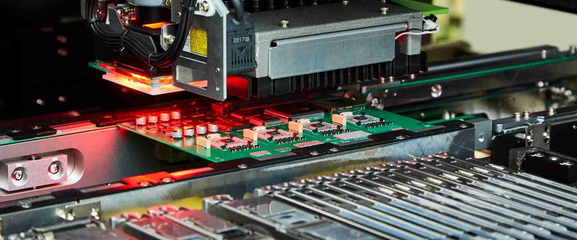
SMT Assembly Process
In Surface Mount Technology (SMT) assembly, precise process control measures are essential to prevent defects and ensure the high reliability and performance of electronic products. Let’s delve deeper into the key control measures for solder paste printing, chip mounting, and reflow soldering.
Process Control Measures in Solder Paste Printing
PCB Quality Control
- Deformation Inspection: PCBs should be inspected for any signs of deformation that could affect the printing process.
- Oxidation Check: Verify that oxidation has not occurred on PCB pads, which can hinder solder paste adhesion.
- Surface Examination: Inspect for scratches, shorts, and copper exposure on the PCB surface that could impact printing quality.
- Printing Uniformity: Ensure that solder paste printing is even and smooth across the PCB surface.
Solder Paste Application and Storage
- Validity Monitoring: Regularly monitor the validity of solder paste to maintain its effectiveness.
- Storage Conditions: Store solder paste in a cold refrigerator and use it within the recommended timeframe to prevent deterioration.
- Temperature and Humidity Control: Maintain workshop temperature at around 25°C and relative humidity between 35% to 75% during solder paste application.
Control Measures for Successful Printing
- Completeness: Verify that solder paste printing is complete, with no areas left uncovered.
- Bridging Prevention: Ensure that there is no bridging between solder paste deposits.
- Printing Thickness: Printing thickness should be uniform and within specified tolerances.
- Pad Edge Inspection: Check for turn-down edges on pads, which can affect component placement.
- Printing Alignment: Verify that there is no deviation in printing alignment, ensuring accurate component placement.
Process Control Measures in Chip Mounting
Mounting Requirement
- Component Quality: Ensure all Surface Mount Devices (SMDs) are used correctly and in sufficient quantities.
- Programming Accuracy: Edit programming parameters accurately to match component specifications.
- Feeder Accuracy: Ensure SMDs and feeders are accurately combined to prevent errors during component placement.
- Equipment Maintenance: Regularly debug and maintain chip mounter to prevent breakdowns during the assembly process.
Solutions to Defects in Chip Mounting
- Equipment Analysis: Analyze the working sequence of the chip mounter to identify potential defects.
- Defect Identification: Identify defects based on their positions, link, and extent, as well as any strange sounds during equipment operation.
- Operational Clarity: Clarify the operation process before addressing defects to ensure effective resolution.
- Positional Inspection: Determine if defects occur at fixed positions, such as the mounting head or nozzle.
- Feeder Inspection: Determine if defects occur at the components feeder or SMDs.
- Redundancy Analysis: Study defect redundancy to determine if they occur at particular amounts or times.
Process Control Measures in Reflow Soldering
Reflow Soldering Requirements
- Temperature Curve: Set a reasonable reflow soldering temperature curve and conduct practical tests regularly to ensure its effectiveness.
- Reflow Direction: Conform reflow direction to the design of the PCB to ensure proper component soldering.
- Belt Vibration Control: Avoid vibration on the transfer belt during the reflow soldering process to prevent component misalignment.
Solder Paste Quality Control
- Metal Oxide Content: Control the metal oxide content in solder paste below 0.05% to prevent solder ball formation.
- Wettability: Ensure sufficient wettability between solder paste, pads, and SMDs to promote strong solder joints.
Soldering Effect Inspection
- Component Soldering Completeness: Verify that soldering is complete on all components.
- Solder Joint Surface: Confirm that solder joints have a smooth surface, indicating proper soldering.
- Joint Shape Examination: Check solder joints for a semi-lunar shape, which indicates proper solder flow.
- Residue Inspection: Verify that no residues are present on the PCB surface after soldering.
- Bridging and Cold Soldering Check: Use a microscope to check for any bridging or cold soldering issues.
Flexible temperature curve adjustments can be made during reflow soldering to accommodate environmental and product performance changes. By implementing these advanced process control measures, manufacturers can achieve higher reliability and performance in SMT assembly, leading to superior quality electronic products.
Improving PCB Assembly Quality with Automated First Article Inspection
In the realm of PCB assembly, the first article inspection (FAI) stands as a pivotal quality assurance step. This process involves building the first PCB by SMT lines and meticulously checking it against the bill of materials (BOM), ensuring the correct programming of SMT pick-and-place machines and accurate component placement into feeders. However, traditional FAI methods are fraught with potential quality issues and often lead to significant waste of manufacturing resources. As contract manufacturers (CMs) cope with the demand for small quantity production of a growing range of PCBs, the pressure to quickly and accurately set up SMT lines after changeovers often results in a less-than-thorough inspection process.
One of the major pitfalls in the traditional FAI process is the risk of improper setups leading to rework due to incorrectly loaded, reversed, or skewed parts after reflow. Most loaders do not verify parts, increasing the likelihood of loading the wrong parts as quickly as the correct ones. To fully grasp the risks associated with the conventional FAI methodology, it is imperative to scrutinize the documentation process.
Documentation and Data Flow in FAI
Customer Provided Data
Data from the customer typically includes:
- Bill of Materials (BOM)
- Assembly Drawing (with reference designators)
- Coordinates file for creating Pick-and-place program
- Gerber files for customizing solder paste stencil
The PCB assembly engineering department inputs the BOM into the FAI system and stores additional documents for manufacturing use. They customize a solder mask and convert BOM and PCB files into CAD files for SMT loaders. The program that designates feeder parts and their locations on the PCB is created, usually automatically from CAD data. This software, often referred to as line-control or line-balancing software, ensures equal parts-loading time for each machine in an SMT line for maximum efficiency.
Risks and Challenges in Traditional FAI
The traditional FAI process is manual and time-consuming, often taking up to 3 hours to inspect all parts on a PCB with 300-400 SMD components. This extended inspection time can lead to idle pick-and-place machines, causing delays in production. Additionally, relying solely on visual inspection and loading diagrams for part identification increases the risk of errors and component misplacement.
Moving Towards Automated First Article Inspection
Automated first article inspection systems offer a more efficient and accurate alternative to traditional manual methods. These systems streamline the inspection process by integrating CAD data, BOM, and pick-and-place data. The operator scans the reflowed PCB into the system, which then imports the CAD data. The system displays an exploded view of each part with its associated data, eliminating the need for manual part location.
Automated FAI systems also import BOM data for cross-checking with pick-and-place data. Any discrepancies are automatically flagged, reducing the risk of human error. The system tracks all parts inspected, ensuring a complete and accurate inspection process. Once the inspection is complete, the known-good sample and data are saved for subsequent runs, enabling quick comparison for future inspections.
Benefits of Automated FAI
- Accuracy: Automated FAI systems ensure accurate part placement and reduce the risk of errors associated with manual inspection.
- Efficiency: By streamlining the inspection process, automated FAI systems save time and improve production efficiency.
- Cost Savings: Reduced rework and improved production efficiency result in significant cost savings for manufacturers.
- Quality Assurance: Automated FAI systems enhance overall quality assurance by providing a thorough and reliable inspection process.
In conclusion, automated first article inspection systems offer a reliable and efficient solution for improving the quality and efficiency of PCB assembly processes. By integrating CAD data, BOM, and pick-and-place data, these systems ensure accurate part placement and reduce the risk of errors, ultimately enhancing the overall quality of PCB assembly.
Why Choose Highleap Electronics for PCB Assembly
Highleap Electronic’s approach to SMT assembly process control aligns with the industry’s best practices, focusing on rigorous control measures at every stage of PCB assembly. From solder paste printing to chip mounting and reflow soldering, Highleap Electronic emphasizes the importance of precision and reliability. By implementing strict control measures, such as PCB quality control checks, solder paste application and storage monitoring, and chip mounting process optimization, Highleap Electronic minimizes the risk of defects and ensures high reliability and performance of electronic products.
Furthermore, Highleap Electronic’s commitment to continuous improvement is evident in its adoption of advanced process control technologies, such as automated first article inspection (FAI) systems. By leveraging these technologies, Highleap Electronic not only improves the efficiency of its inspection processes but also enhances the accuracy and reliability of its PCB assembly processes. This dedication to quality and innovation makes Highleap Electronic a preferred choice for companies seeking reliable and high-quality PCB assembly services.
Conclusion
The increasing reliance on Surface Mount Technology (SMT) assembly in the electronics industry underscores the critical importance of performance and reliability in electronic products. High-quality SMT assembly not only reflects the standard of manufacturing workshops but also ensures the long-term development of electronics. To achieve optimal product performance and ensure a rational, regulatory, and standardized manufacturing process, it is essential to establish a robust process control system compatible with practical manufacturing requirements.
Highleap Electronic, with its expertise in PCB assembly, recognizes the significance of rigorous process control in SMT assembly. By implementing key control measures, such as those for solder paste printing, chip mounting, and reflow soldering, Highleap ensures the prevention of defects and the maintenance of high reliability and performance of electronic products. Additionally, Highleap’s commitment to quality is further demonstrated through the utilization of advanced process control measures, including automated first article inspection systems, to enhance the quality and efficiency of PCB assembly processes, ultimately leading to the delivery of superior quality electronic products.
PCB & PCBA quick quote
Related Articles

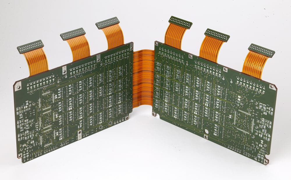
Advantages of Flexible PCB and Rigid-Flex PCB
Rigid-Flex Boards--Rigid-Flex PCBAccording to the IPC 6013 standard, flexible boards are classified into single-sided, double-sided, multilayer, and rigid-flex boards. The manufacturing process of rigid-flex boards includes material preparation, forming, etching,...
PCB, Multilayer FPC, Flex rigid Multi-layer PCB Fabrication
[pac_divi_table_of_contents title="On this article" default_state="closed" included_headings="off|on|on|off|off|off" exclude_headings_by_class="on" active_link_highlight="on" level_markers_3="icons" title_container_padding="10px|15px|10px|15px|true|false"...

The Differences between PET and Pl Material of Flexible PCB
[pac_divi_table_of_contents title="On this article" default_state="closed" included_headings="off|on|on|off|off|off" exclude_headings_by_class="on" active_link_highlight="on" level_markers_3="icons" title_container_padding="10px|15px|10px|15px|true|false"...
Take a Quick Quote