
Back to blog
IPC Class 2 vs Class 3 for PCB Fabrication Drawings

In simple terms, IPC Class 2 is generally used for dependable commercial and industrial electronics where reliable performance is important but uninterrupted service is not mission-critical. IPC Class 3 is used for high-reliability products where failure is unacceptable and where the board must perform consistently in demanding operating conditions.
Use this page when the IPC class needs to be written into fabrication drawings, inspection notes, or purchase documents. For a broader standards comparison, see the IPC Class 2 vs Class 3 comparison; for production control, pair the requirement with Highleap’s PCB quality assurance process before quoting.
This guide explains the real difference between IPC Class 2 and Class 3, how each class affects PCB design, CAM documentation, manufacturing, and soldering, when each class makes sense, and how to choose the right one before you send the job for PCB DFM and production.
Quick Answer for IPC Class 2 vs Class 3
If your PCB is for commercial electronics, standard industrial controls, communications equipment, computing hardware, or other products where good performance and reasonable service life are required, IPC Class 2 is often the right fit.
If your PCB is for critical medical equipment, aerospace, defense, harsh-environment electronics, or any product where field failure is unacceptable, IPC Class 3 is usually the more appropriate standard.
That is the short answer. The better answer depends on five practical issues: the consequence of failure, the operating environment, the expected service life, customer or industry requirements, and whether the design and manufacturing process can actually support the chosen class.
What IPC Class 2 Really Means in a Production Project
IPC Class 2 applies to dedicated service electronic products. These boards still need to perform reliably and maintain a reasonable service life, but they are not usually expected to support life-critical, mission-critical, or extreme-environment operation.
Typical Class 2 products include:
- consumer electronics
- commercial communication equipment
- general computing hardware
- non-critical industrial electronics
- standard control boards
- cost-sensitive production programs
For these projects, the goal is still good manufacturing quality. The difference is that the process window is more forgiving than Class 3. Minor workmanship variation may still be acceptable as long as function, safety, and intended service performance are not materially affected.
That is why Class 2 is common in projects that need a practical balance between quality, scalability, and total cost in PCB fabrication.
What IPC Class 3 Really Means in a Production Project
IPC Class 3 is intended for high-performance electronic products that require a higher level of reliability and are expected to keep working under more demanding conditions. These boards are built with tighter acceptance criteria and lower tolerance for marginal workmanship because the cost of failure is much higher.
Typical Class 3 applications include:
- critical medical electronics
- aerospace and avionics systems
- military and defense electronics
- high-reliability industrial control systems
- electronics exposed to harsh environments
- long-life systems where service interruption is costly or dangerous
In these cases, the board is not just expected to work at shipment. It is expected to continue working with much less tolerance for latent weakness, poor soldering, marginal hole quality, or incomplete process control.
Projects in areas such as medical PCB manufacturing, aerospace PCB, and military PCB often start with these reliability discussions much earlier because standard commercial assumptions are not enough.
The Real Difference Between IPC Class 2 and Class 3
The most important difference is not the label. It is the allowable risk level.
Reliability expectation :Class 2 is designed for products that should work reliably in normal use. Class 3 is designed for products where uninterrupted or highly dependable operation matters much more, and where hidden workmanship weakness is less acceptable.
Acceptance criteria: Class 3 requires tighter control of workmanship and less tolerance for marginal conditions. That affects plating quality, conductor integrity, solder joints, annular ring condition, cleanliness, and overall consistency.
Process discipline:Class 3 usually demands more disciplined control in engineering review, CAM verification, fabrication, assembly, and final inspection. Weak documentation or borderline design decisions are more likely to cause issues when the target is Class 3.
Business impact:Class 3 adds cost and process effort, but the extra control may be completely justified if the field risk is high. For a non-critical product, that same extra cost may not create enough value to justify the tighter build standard.
How the IPC Class Decision Affects PCB Design
This is one of the biggest gaps in most articles on the subject. The IPC class does not only matter to the factory. It also affects design decisions before Gerber files are ever released.
If the target is Class 3, the design team often needs to pay closer attention to:
- annular ring margins
- hole quality tolerance
- pad-to-copper spacing
- via structure reliability
- layer registration margin
- plating robustness
- cleanliness-sensitive layout choices
- mechanical and thermal reliability
A PCB layout that is acceptable for a Class 2 project may still become risky if the customer later asks for Class 3. That is why the class should be discussed during PCB design, not after quoting is nearly complete.
If the class requirement is added too late, the project may need data revision, CAM clarification, or in some cases real design changes before it is comfortable to manufacture.
How the IPC Class Decision Affects CAM Engineering Review
CAM engineering is where many class-related problems become visible. At this stage, the factory checks whether the released data package really supports the requested class level. A design may look correct in CAD, but CAM review often reveals whether the margins are sufficient for actual production.
For a higher class target, CAM engineers will pay closer attention to issues such as:
- annular ring adequacy after drill tolerance and registration shift
- hole-to-copper spacing
- solder mask sliver width
- pad integrity around dense features
- conductor spacing under process tolerance
- data consistency between fabrication notes and Gerber output
- whether the stackup and process assumptions match the required reliability level
This is one reason the class decision cannot be treated as a simple quote checkbox. It directly affects whether the CAM package is easy to approve or whether it creates engineering questions, lead time loss, or rework before the job even starts.
How the IPC Class Decision Affects Soldering and Assembly
Another weak point in many Class 2 vs Class 3 articles is that they talk mostly about fabrication and almost ignore soldering. In reality, assembly also feels the effect of the class target.
Class 3 expectations usually mean lower tolerance for workmanship conditions that could weaken solder joint reliability over time. That affects how the manufacturer approaches:
- solder joint appearance and acceptance
- process stability in PCB assembly
- rework tolerance
- cleanliness control after assembly
- inspection depth and consistency
- verification of critical joints or hidden interconnects
For this reason, class selection should not be decided only by the bare board team. It should be aligned with fabrication and assembly expectations together, especially when the project is moving into controlled builds or customer acceptance testing.
How Class 2 vs Class 3 Changes Cost and Lead Time
Many users search this topic because they want to know whether Class 3 will noticeably raise the price. In most real projects, the answer is yes, but not because of one single cost item.
The cost increase usually comes from a combination of:
- tighter process control
- more detailed engineering review
- stricter inspection requirements
- lower tolerance for marginal output
- more careful documentation and traceability
- potential yield sensitivity in more demanding builds
That means Class 3 can affect both the board cost and the production rhythm. It may add value when the application truly needs that risk reduction. But if the end product does not justify it, it can simply increase manufacturing burden without meaningful business return.
Class 3 Does Not Automatically Mean Military or Aerospace Grade
This is one of the biggest misunderstandings in the market. IPC Class 3 is a high-reliability class, but it does not automatically mean the project meets every military, aerospace, or defense requirement.
Some projects go beyond standard Class 3 and also require customer-specific documentation, traceability, first article review, extra inspection controls, or sector-specific quality systems. So the real question is not only “Can you build Class 3?” but also “Does this project require anything beyond standard Class 3?”
If that is not clarified early, the supplier may quote one thing while the customer expects something stricter, which can create major alignment problems later.
How to Choose the Right Class for Your PCB Project
The best way to choose between Class 2 and Class 3 is to answer a few practical questions.
What happens if the board fails:If failure mainly means inconvenience, repair, or routine replacement, Class 2 may be enough. If failure means safety exposure, mission interruption, system shutdown, or severe business loss, Class 3 becomes much more reasonable.
What environment will the product face:Boards operating in controlled commercial environments usually do not need the same reliability margin as boards exposed to vibration, moisture, thermal cycling, or other harsh conditions.
How important is long-term service stability:If the product must stay dependable for long deployments or under limited maintenance access, the extra controls of Class 3 may be justified.
Does the market or customer already define the requirement:In some sectors, the decision is driven by customer or industry expectation, not by internal preference alone.
Can the design and manufacturing flow realistically support the class:It is not enough to request a higher class. The PCB design, CAM preparation, fabrication controls, and soldering process all need to support it.
Common Mistakes When Comparing Class 2 and Class 3
- assuming Class 3 is automatically the best choice
- assuming Class 2 is always enough for industrial products
- deciding the class after layout is already finished
- ignoring the effect on CAM engineering review
- ignoring the effect on soldering and assembly quality control
- treating standard Class 3 as identical to every military or aerospace requirement
- focusing only on board price instead of failure cost
The right class is the one that matches the real reliability need without creating unnecessary process burden.
What to Confirm with Your PCB Supplier Before Ordering
Before releasing the order, engineers and buyers should confirm:
- which IPC class the quote is based on
- whether the current PCB design supports that class target
- what CAM review risks are most likely for this design
- how fabrication and assembly controls change between Class 2 and Class 3
- whether extra documentation beyond standard class requirements is needed
- how the class will affect cost and lead time
These questions turn the class decision into a real production plan instead of just a standards discussion.
Conclusion
IPC Class 2 and Class 3 are not just labels on a quote. They influence how the PCB is designed, how CAM engineers review the data, how tightly fabrication is controlled, how soldering is judged, and how much risk the final product can tolerate in the field.
Class 2 is usually the right choice for dependable commercial and industrial electronics where cost and reliability need to stay balanced. Class 3 is the better fit for high-reliability products where failure is not acceptable and where tighter design, manufacturing, and assembly control are justified.
The best decision is not made by choosing the highest class automatically. It is made by matching the class to the product function, operating environment, service expectations, and real consequence of failure.
If that decision is made early, PCB design, CAM preparation, supplier communication, and production planning all become much smoother.

Related Articles
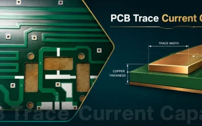
PCB Trace Current Capacity: Width, Copper Weight, and IPC-2221
Learn PCB trace current capacity by copper weight, trace width, layer position, voltage drop, and DFM limits before ordering a board.
EAGLE PCB Software: Is It Free, EAGLE vs KiCad, and How to Export Gerber Files
Compare EAGLE PCB software with KiCad and Altium, then export Gerber, drill, and assembly files for PCB manufacturing review.
Altium CircuitMaker: Is It Free, How Does It Compare, and How to Export Gerbers for Manufacturing
Use Altium CircuitMaker for PCB design, compare it with KiCad and Altium Designer, and prepare clean Gerber files for manufacturing.