
Back to blog
5 Ways and Benefits of Determining LED Polarity

Simple schematic diagram of LED polarity judgment
Proper placement, labeling, and orientation of components on a Printed Circuit Board (PCB) help reduce common issues such as short-circuiting and other electrical problems. Ensuring correct orientation of components, particularly LEDs, is crucial for the board’s functionality and longevity. In this article, we will delve into the details of LED polarity, specifically the anode and cathode, and provide practical guidance on correctly positioning them on your boards.
Understanding LEDs
Light Emitting Diodes (LEDs) are semiconductors that emit light when an electrical current passes through them. Like all diodes, LEDs only allow current to flow in one direction, which is essential for their operation. This one-way current flow, or polarity, is a crucial aspect of their design and must be carefully managed during PCB design and assembly to ensure optimal functionality. Proper orientation of LEDs on a PCB is key to achieving the desired performance and longevity of the component.
LED Polarity: Anode and Cathode
LEDs have two primary terminals: the anode and the cathode. Understanding the function and correct positioning of these terminals is critical:
- Anode: The positive side of the LED, where the electrical current enters.
- Cathode: The negative side of the LED, where the electrical current exits.
Identifying Anode and Cathode
Properly identifying the polarity of LEDs is crucial for their functionality when placed on a Printed Circuit Board (PCB). Incorrect polarity can lead to non-functional LEDs and potential issues in your circuit. Here’s how you can ensure the correct orientation:
- Lead Length: The simplest and most straightforward method to check LED polarity is by observing the length of the leads. Typically, the longer lead is the anode (positive), and the shorter lead is the cathode (negative). This method is effective with new LEDs that haven’t been modified.
- Flat Side Identification: Another visual indicator is the flat side on the casing of an LED. This side typically marks the cathode. The lead closest to this flat side is the negative terminal, making it easy to identify without any special tools.
- Internal Structure Inspection: By looking inside the LED, you can observe two metal plates of different sizes. The smaller plate is usually connected to the anode, and the larger plate to the cathode. This method may require a magnifying tool for clear visibility.
- Multimeter Testing: A multimeter can be used to definitively determine the polarity. By setting the multimeter to its diode function and touching the leads with the probes, the LED will light up if correctly connected (red probe to anode, black probe to cathode). If there’s no light, switch the probes.
- Using a Coin Cell Battery: This practical method involves using a small coin cell battery to establish polarity. Place the battery between the leads of the LED; if the LED lights up, the lead touching the positive side of the battery is the anode. If it doesn’t light up, reverse the battery.
Each of these methods provides a reliable way to determine the polarity of LEDs, ensuring they are correctly installed for optimal performance.
How to detect LED polarity is explained in the video
Practical Tips for Correct LED Placement
Visual Inspection:Always visually inspect LEDs before placement. Ensure the longer pin (anode) is correctly aligned with the designated positive pad on the PCB. This step helps prevent common placement errors and ensures the LED will function properly.
Use of Markings:Rely on the positive (+) and negative (-) signs on the PCB for guidance. Some PCBs might also have arrows or other symbols indicating the correct orientation. These markings are crucial for ensuring the correct placement of the LEDs.
Check Manufacturer Specifications:Different manufacturers may use varying symbols or markings to indicate LED polarity. Always refer to the datasheet for specific information on LED polarity. This ensures that you understand and correctly interpret the markings used by the manufacturer.
Consistency in Orientation:Maintain consistency in LED orientation across the entire PCB to avoid confusion and potential errors during assembly. Consistent orientation simplifies the assembly process and reduces the likelihood of mistakes.

Simple schematic diagram of LED polarity judgment
Addressing Ambiguity and Inconsistency
Ambiguity in LED markings and orientation standards can lead to errors. Here are common issues and how to address them:
- Interchanged Diode Markings: Different manufacturers may use varying symbols for anode and cathode. Always cross-check with the datasheet and ensure uniformity in your assembly process.
- Discarding of Markings: Some manufacturers might discard traditional markings in favor of dots or bent outlines. Familiarize yourself with these alternative markings to avoid mistakes.
- THT vs. SMT Orientations: Through Hole Technology (THT) and Surface Mount Technology (SMT) have distinct orientation practices. For THT, a longer pin or flat edge indicates the cathode. In SMT, markings at the end of the cathode help identify the correct orientation.
Correct LED orientation on PCBs significantly enhances their performance and durability. By ensuring that LEDs are oriented properly, potential electrical issues such as short-circuiting are minimized, thereby optimizing device performance and extending the lifespan of the components.
Moreover, maintaining a consistent orientation during the placement of LEDs streamlines the soldering and assembly processes. This uniformity helps in reducing errors and the need for rework, while also ensuring that each diode connects correctly to its intended voltage source, which supports efficient and smooth current flow for optimal operation.

LED with polarity symbol on PCB
Why Choose Highleap Electronic for Your PCB Manufacturing and Assembly Needs?
At Highleap Electronic, we provide complete, reliable PCB manufacturing and assembly services designed to meet your specific requirements. Here’s why clients trust us:
- Automated Precision Assembly: Our advanced automated SMT (Surface Mount Technology) machines and automatic insertion equipment for Through-Hole Technology (THT) ensure precise and consistent placement of all components, including LEDs, across every PCB. This automation reduces errors, improves efficiency, and ensures reliable performance for both prototypes and large-scale production.
- Cutting-Edge Inspection Systems: We use Automated Optical Inspection (AOI) and X-ray inspection technology to guarantee 100% accuracy in LED polarity and component placement, eliminating rework and ensuring your designs function perfectly.
- Comprehensive End-to-End Service: From design consultation and material selection to manufacturing and assembly, we manage every step of the process seamlessly. This streamlined approach ensures faster turnaround times and exceptional results.
- Expertise in Complex PCB Designs: Whether your project requires SMT, THT, or mixed-technology PCBs, we have the expertise to handle even the most challenging designs while maintaining top-notch quality and reliability.
- Flexible Production Options: We support small-batch prototyping and high-volume manufacturing, giving you the flexibility to scale your projects without compromising quality or delivery timelines.
At Highleap Electronic, we combine modern automated processes, industry expertise, and rigorous quality control to deliver PCBs that meet your exact needs. Whether you’re creating LED-heavy boards or intricate flight controller designs, we ensure precision, efficiency, and value at every stage.
Conclusion
Correct placement and orientation of LEDs on PCBs are crucial for preventing electrical issues and ensuring optimal device performance. By understanding the functions of anode and cathode, using practical identification methods, and addressing potential ambiguities, you can achieve precise and efficient LED placement. These best practices will enhance the reliability and longevity of your electronic devices, ultimately benefiting your target audience in need of high-quality LED solutions.
FQA
1.What happens if an LED is incorrectly oriented on a PCB?
Incorrectly orienting an LED on a PCB can lead to several issues. Primarily, the LED will not function because the current cannot flow in the wrong direction. This can lead to diagnostic challenges on the board and potential delays in troubleshooting other components.
2.Why is it important to verify LED polarity before finalizing a PCB design?
Verifying LED polarity before finalizing a PCB design is crucial to prevent manufacturing errors and ensure the functionality of the board. Early verification helps avoid costly reworks and ensures that the assembly process is smooth, preventing potential damage to other components.
3.Can LED polarity be determined without a multimeter?
Yes, LED polarity can often be determined without a multimeter by examining physical characteristics such as pin length and the presence of a flat notch. However, using a multimeter is a more foolproof method, especially when visual indicators are ambiguous or too small to be noticed easily.
4.How do manufacturers typically indicate LED polarity on datasheets?
Manufacturers usually indicate LED polarity on datasheets with diagrams showing the physical layout of the LED, including pin configurations and polarity markings. These often include detailed descriptions of each pin and any special characteristics that help identify the anode and cathode.
5.What are some common mistakes to avoid when placing LEDs on a PCB?
Common mistakes when placing LEDs on a PCB include reversing the anode and cathode, placing the LED in a location that doesn’t align with the board’s voltage sources, and ignoring the manufacturer’s specific orientation requirements. Ensuring strict adherence to the schematics and manufacturer guidelines can mitigate these errors.

Recommended Posts
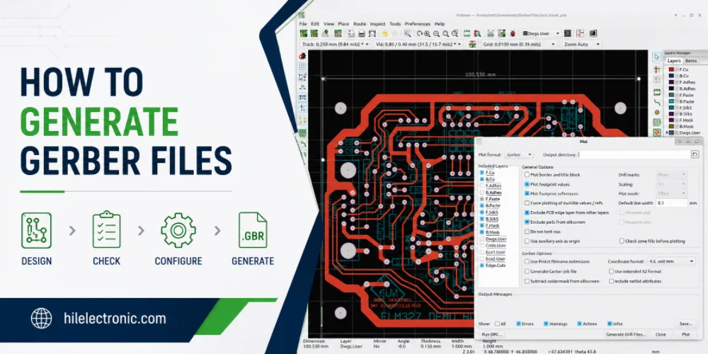
How to Generate Gerber Files for PCB Manufacturing
Figure 1. how to generate Gerber files image for Highleap...
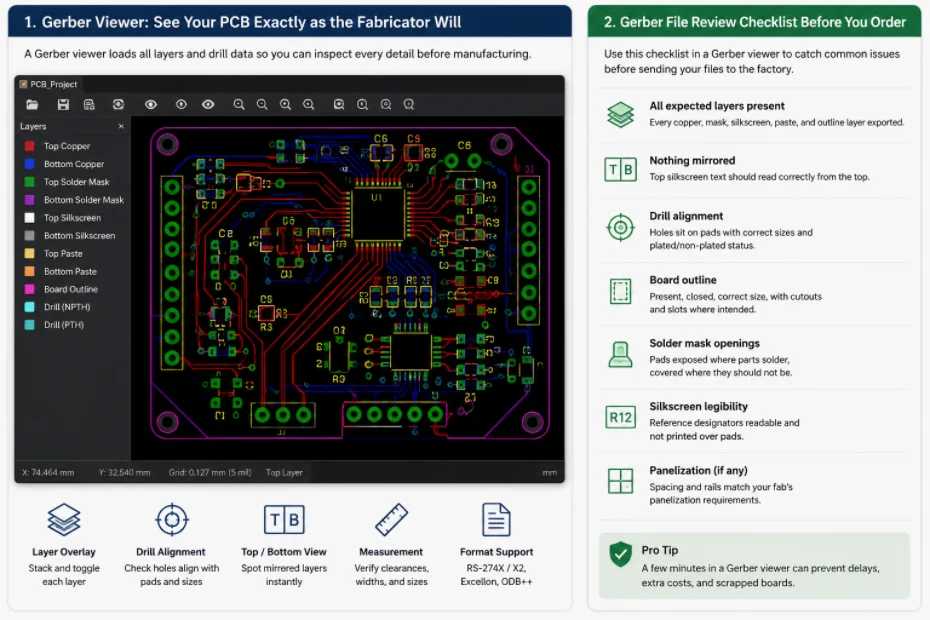
Gerber File Review Checklist: How to Check PCB Files Before You Order
Figure 1. Gerber file review catches missing layers, drill...
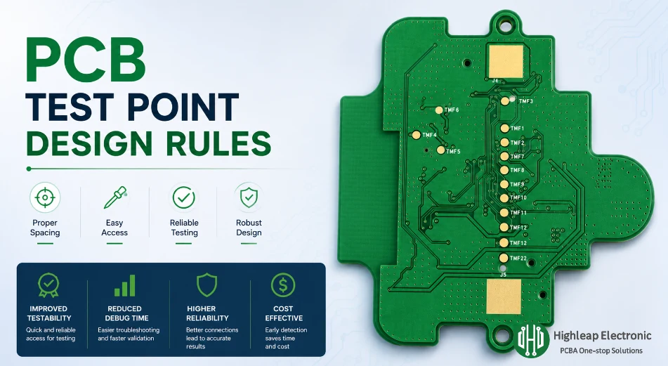
PCB Test Point Design Rules for Debug and ICT
Figure 1. PCB test point design rules help make debugging,...

PCB Jumper Wire: Uses, Types, and Design Tips
Figure 1. PCB jumper wires are useful for prototypes and...
How to get a quote for PCBs
Let us run DFM/DFA analysis for you and get back to you with a report.
You can upload your files securely through our website.
We require the following information in order to give you a quote:
-
- Gerber, ODB++, or .pcb, spec.
- BOM list if you require assembly
- Quantity
- Turn time
In addition to PCB manufacturing, we offer a comprehensive range of electronic services, including PCB design, PCBA (Printed Circuit Board Assembly), and turnkey solutions. Whether you need help with prototyping, design verification, component sourcing, or mass production, we provide end-to-end support to ensure your project’s success. For PCBA services, please provide your BOM (Bill of Materials) and any specific assembly instructions. We also offer DFM/DFA analysis to optimize your designs for manufacturability and assembly, ensuring a smooth production process.