Back to blog
What is a Cold Joint Solder and How Can You Prevent it?

PCB Soldering
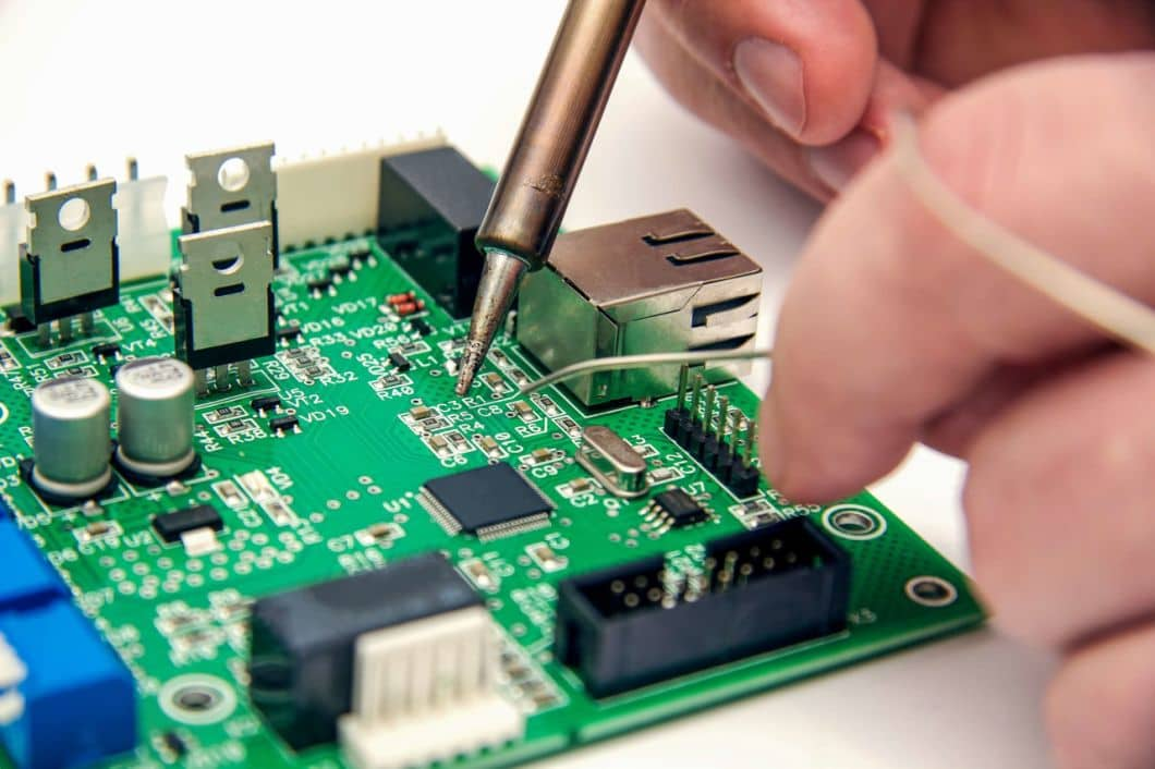
Soldering is a critical process in PCB assembly and manufacturing, where electronic components are mounted on the circuit board using a combination of Tin (Sn) and Lead (Pb). Whether you’re using Surface Mount Technology (SMT) or Through-hole Technology (THT), soldering plays a pivotal role in the assembly process.
Significance of Soldering in PCB Assembly
Soldering is at the heart of designing and creating a circuit board. Its importance in PCB assembly services cannot be overstated. PCB materials are soldered using various methods by PCB manufacturers, including wave soldering, through-hole reflow soldering, and SMT soldering. However, one of the most common issues encountered during PCB soldering is cold solder joints, which significantly impact the performance of the printed circuit board and can increase the cost of assembly.
Understanding Cold Solder Joints
A cold solder joint is a defect in a soldered joint that occurs when the soldering process does not create a strong bond between the components being joined. This can happen when the soldering iron and solder wire are not at the correct temperature, leading to incomplete melting of the solder and inadequate wetting of the surfaces to be joined.
One of the key factors in preventing cold solder joints is ensuring that the soldering iron is at the correct temperature for the type of solder being used. Different types of solder require different temperatures to melt properly, so it is important to use a soldering station with adjustable temperature settings.
Additionally, the surfaces being soldered must be clean and free of any oxidation or contamination that could interfere with the soldering process. Proper fluxing is also essential, as it helps to remove oxidation and promote the wetting of the solder.
Common Soldering Issues
In addition to the common issue of cold solder joints, there are several other soldering problems that can occur during PCB assembly. These issues can impact the functionality and reliability of the finished circuit board:
- Disturbed Joint: This problem occurs when there is a disturbance at the joint before the solder paste solidifies. This can happen if the components being soldered are moved or disturbed while the solder is still in a molten state. A disturbed joint can lead to poor electrical connections and reliability issues.
- Solder Bridge: A solder bridge occurs when two adjacent solder joints unintentionally connect, creating a short circuit. This can happen if there is too much solder applied or if the solder flows between components that are too close together. Solder bridges can cause the circuit to malfunction and can damage components if not corrected.
- Overheated Joint: An overheated joint occurs when the flux on the circuit board becomes too hot, often due to the solder wire failing to melt properly. This can happen if the soldering iron is too hot or if it is left on the joint for too long. Overheating can damage the flux and solder, leading to poor solder joints and potential reliability issues.
- Insufficient Wetting: Insufficient wetting occurs when the solder does not properly flow and adhere to the surfaces being soldered. This can happen if the surfaces are not clean or if the soldering iron is not at the correct temperature. Insufficient wetting can lead to weak solder joints and poor electrical connections.
- Excessive Solder: Applying too much solder can lead to several issues, including solder bridges and solder balls. Solder bridges occur when too much solder connects two adjacent joints, while solder balls are small balls of solder that can form on the surface of the circuit board. Excessive solder can cause shorts and other reliability issues.
- Lack of Flux: Flux is used to clean and prepare the surfaces being soldered, helping the solder to flow and adhere properly. A lack of flux can lead to poor wetting and weak solder joints. It’s important to use the right type and amount of flux for the soldering job.
- Component Damage: Excessive heat or prolonged heating can damage sensitive components, such as integrated circuits (ICs) or surface-mount devices (SMDs). It’s important to use proper soldering techniques and tools to avoid damaging components during soldering.
- Uncontrolled Temperature: Temperature control is crucial in soldering to ensure that the solder melts properly and flows evenly. An uncontrolled temperature can lead to overheating, cold solder joints, and other soldering issues. Using a soldering station with adjustable temperature settings is recommended.
By understanding and addressing these common soldering issues, you can improve the quality and reliability of your PCB assemblies. Using proper techniques, tools, and materials can help prevent these issues and ensure that your solder joints are strong and reliable.
Types of Cold Solder Joints
There are different types of cold solder joints that can be observed when handling a circuit board, each with unique impacts and fixes:
- Distributed Cold Joint: This occurs when the soldering iron moves when the solder alloy is placed on a specific area of the board, resulting in a scattered appearance.
- Cracked Solder Joint: Inadequate solder or mechanical forces can cause some cold solder connections to break, leading to a loose component pin and broken electrical conduction circuits.
- Dry Solder Joint: This type of cold solder connection is characterized by a lack of solder, resulting in open connections and erratic current flow.
Identifying Cold Solder Joints
Cold solder joints can be a common issue in PCB assembly, impacting the overall functionality and reliability of the circuit board. To ensure the quality of your solder joints, it’s important to be able to identify cold solder joints. Here are some common methods used for identifying cold solder joints:
- Visual Inspection: One of the simplest methods for identifying cold solder joints is through visual inspection. Cold solder joints often appear dull, grainy, or rough compared to properly formed solder joints, which are typically shiny and smooth. Additionally, cold solder joints may have incomplete coverage of the solder pad or component lead, indicating a lack of proper melting and bonding.
- Magnification: Using a magnifying glass or microscope can help in inspecting solder joints more closely, making it easier to identify any signs of cold soldering, such as poor wetting or incomplete bonding.
- Multimeter Testing: A multimeter can be used to test the continuity and resistance across a solder joint. A cold solder joint may show higher resistance or no continuity, indicating a poor connection.
- Tap Test: Gently tapping the solder joint with a non-conductive tool, such as a wooden dowel, can help identify loose or poorly bonded solder joints. A cold solder joint may produce a dull sound compared to a properly bonded joint, which produces a solid, metallic sound.
- Thermal Imaging: Using a thermal camera or thermal imaging tool can help identify cold solder joints by detecting temperature variations in the solder joints. Cold solder joints may appear cooler than surrounding joints, indicating a lack of proper heating and bonding.
- X-ray Inspection: For more advanced and thorough inspection, X-ray inspection can be used to detect cold solder joints and other soldering defects that may not be visible to the naked eye.
By using these methods, you can effectively identify cold solder joints and take the necessary steps to rework or repair them, ensuring the overall quality and reliability of your PCB assemblies.
Preventing Cold Solder Joints
To avoid cold solder joints during PCB assembly, it’s essential to maintain effectiveness and quality in soldering. Here are some best practices to help you avoid cold solder joint issues:
Use the Correct Equipment: Use high-quality soldering tools, including a soldering iron that is easy to control and provides regulated heat delivery. Ensure the soldering iron comes from a reliable source to ensure quality results.
Temperature Control: Maintain a moderate heat state during soldering to ensure the solder wire melts properly. Proper temperature control is crucial for achieving good solder joints.
Use Sufficient Amount of Solder: Avoid over-soldering or using too little solder, as both can lead to cold solder joints. Prepare enough solder for the operation and apply it evenly to ensure good bonding.
Environment: Create a stable and secure environment for soldering, free from sources of vibration. This helps ensure that the solder joints are formed properly and securely.
Cleaned Soldering Iron: Regularly clean the soldering iron to remove any debris or contaminants that may affect soldering quality. Keep soldering tools in a dust-free environment to prevent contamination.
Good Power Supply: Ensure the soldering iron or gun has a constant and reliable power supply to prevent interruptions during soldering.
Consider Lead-free Soldering: Consider using lead-free solder wire, which is more environmentally friendly and complies with green electronics standards such as RoHS.
Time Management: Be patient during the soldering process and allow enough time for the soldering iron to heat up and melt the wire properly. Rushing the process can lead to poor solder joints.
User Experience: Have confidence in your soldering skills and experience. Follow the reflow profile instructions carefully and avoid panicking, as this can lead to mistakes.
Conclusion
Understanding and addressing cold solder joints are critical for ensuring the reliability and performance of PCB assemblies. These joints, characterized by insufficient heat during the soldering process, can lead to increased electrical resistance and potential reliability issues in electronic assemblies.
Preventing cold solder joints involves using the correct equipment, maintaining proper temperature control, using a sufficient amount of solder, ensuring a clean soldering environment, and following best practices for soldering. By adhering to these guidelines, you can minimize the risk of cold solder joints and ensure the integrity of your PCB assemblies.
PCB & PCBA quick quote
Related Articles

Flexible PCB Cost Optimization Strategy
flexible PCBIn the realm of contemporary electronics, the proliferation of flexible PCBs stands as a testament to the industry's evolution toward miniaturization and functionality. Unlike the more traditional rigid PCBs, which benefit from simpler production...

Enhance Your PCBA Project:Comprehensive Guide to DIP Package
DIP PCB design drawingIn the rapidly evolving world of electronics manufacturing, understanding the impact and evolution of component packaging technologies such as the Dual In-Line Package (DIP) is crucial for any PCBA project. Originally introduced by Fairchild...

High Volume Turnkey PCB Assembly Services
PCB assembly servicesPrinted Circuit Board Assembly (PCBA) is a critical process in electronics manufacturing, where various electronic components are soldered onto a PCB to create a functional electronic device. This comprehensive guide explores the PCB assembly...
Take a Quick Quote


