
Back to blog
Rigid Flex PCB Design: The Definitive Guide
Whether you are new to the world of rigid-flex PCB design or a seasoned professional seeking deeper insights, this comprehensive guide is your definitive resource. We will cover a wide range of topics related to rigid-flex printed circuit board (PCB) design, from basic definitions and classifications to advanced design considerations, materials, manufacturing processes, and more. By the end of this guide, you’ll have a thorough understanding of rigid-flex PCBs, enabling you to excel in their design and implementation. Let’s dive right into the core of this topic.
What is a Rigid Flex PCB?
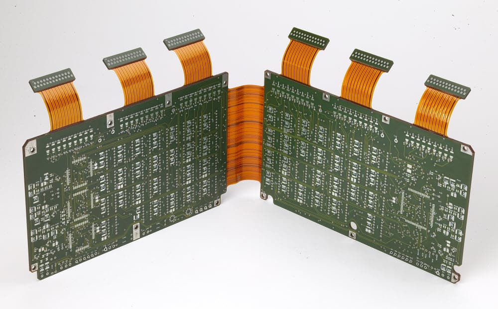
A rigid-flex printed circuit board (PCB) is a specialized board that combines the features of both rigid and flexible PCB technologies within a single application. Most rigid-flex PCBs consist of multiple layers of flexible circuit substrates attached to rigid boards. The positioning of these flexible layers can be either on the outer or inner sections of the board, depending on the specific design requirements.
Rigid-flex PCBs are essentially a network of conductors with circuit traces on a flexible insulating film, combining the advantages of both rigid and flexible circuits. The rigid portions of the board accommodate most components, while the flexible sections serve as interconnections between different rigid areas. This technology initially found its roots in space programs where saving space and reducing weight were critical. Today, you can encounter rigid-flex PCBs in numerous applications, particularly those that demand compactness and weight reduction, such as tablets, mobile phones, radios, pagers, and computers.
The circuits on a rigid-flex PCB are typically composed of a thin layer of conductors on the surface of an insulating board known as substrates. Various components on the surface connect to these substrates via solder connections.
Types of Rigid-Flexible Printed Board Circuits

Rigid-flex PCB design comes in several categories, each suited to specific applications. It’s crucial to select the right type of rigid-flex PCB design to match the requirements of your application. Let’s explore the different kinds of rigid-flex PCB designs available:
Flexible PCB: These boards use flexible plastic substrates, enabling them to bend and flex without breaking. While they are more expensive to manufacture compared to rigid PCBs, their flexibility makes them highly advantageous. Flexible PCBs are particularly useful for reducing bulky and heavy wiring in advanced technologies and equipment, such as satellites. They come in various forms, including single-sided, double-sided, and multilayer flexible PCBs.
- Single Sided Flex: In this type, the conductive layer with copper material is present on one side of the board. Single-sided flexible PCBs are suitable for dynamic applications and are cost-effective and easy to assemble. They require only one type of tooling for assembly, simplifying the production process.
- Double Sided Flex: This extension of the single-sided PCB has copper conductors on both sides of the board, with copper insulators connecting them through vias or plated through holes (PTH). Double-sided flex PCBs are easy to manufacture, lightweight, and can be reproduced quickly.
- Multilayer Flex: As the name suggests, these boards feature more than two copper conductive layers, often up to 10 layers. Vias or plated through holes are used to establish connections between these layers. Multilayer flexible PCBs are essential for applications requiring high-density connector PCBs and routing through confined spaces.
Rigid-flex PCB: This type combines rigid and flexible printed circuit boards into a single structure. The flexible part seamlessly integrates with the rigid section through plated through holes. Rigid-flex PCBs are known for creating smaller interconnect areas, reducing the risk of failure during application. They also prevent the rigid part from twisting and breaking. You can commonly find them in computer motherboards and other electronic devices.
Rigid Flex Circuit Board Material
The selection of materials plays a crucial role in the construction of rigid-flex circuit boards. These boards consist of stacked flexible substrate materials with copper conductors, which are laminated together using adhesives under heat and pressure. Choosing the right materials is essential to ensure durability and strength. Here are some factors to consider when selecting materials for rigid-flex PCBs:
-
Dimensional Stability: The material should maintain its shape and dimensions under varying conditions.
-
Thermal and Heat Resistance: It’s essential to choose materials that can withstand the expected temperature ranges in the application.
-
Electrical Properties: Materials should have appropriate conductivity for electrical signals to pass through.
-
Flexibility: Flexible portions of the board require materials that can bend without losing their structural integrity.
-
Chemical Resistance: Consider the materials’ resistance to chemicals that may be encountered in the application.
Rigid Flex PCB Stack-up
Building a multilayer PCB is akin to assembling LEGO pieces. Components must fit together smoothly, following precise instructions for a successful connection. Multilayer PCBs, with their complex stack-ups, are integral to many applications. Let’s explore the materials commonly found in rigid-flex PCB designs:
Flexible Material: This technology involves assembling electronic circuits on flexible plastic substrates, such as PEEK, polyimide, or transparent polyester capable of conducting electricity. Polyester (PET) is a popular choice due to its flexibility, electrical conductivity, resistance to moisture, and chemical properties, making it suitable for industrial environments. While flexible materials offer advantages such as replacing rigid connectors and boards, they also have disadvantages, including higher costs, susceptibility to damage, complex assembly, and limited reworking or repair options.
Rigid Material: Manufacturers use various materials for the rigid portions of rigid-flex PCBs, depending on the application’s requirements. Factors to consider when choosing rigid materials include reliability, shelf life, manufacturing methods, budget, and cost considerations. One common material is woven fiberglass with epoxy resin, but it is not suitable for applications with frequent shocks, movements, or vibrations. Polyimide, a flexible and robust thermoset material, is a preferred choice due to its toughness, versatility, resistance to vibrations and heat, making it suitable for challenging environments.
Conductor Material: Copper is the preferred conductor material for rigid-flex PCBs. It is readily available, highly workable, and conducts electricity efficiently. Manufacturers can choose between electro-deposited copper and rolled copper foil, both available in various thicknesses, sizes, and weights. Surface treatment is applied to enhance copper foil longevity, which includes applying a thin layer of zinc to prevent degradation, improve adhesion, increase strength, and protect against oxidation.
Adhesive Types: Adhesives are essential for laminating flexible and rigid materials together to create a unified PCB structure. The choice of adhesive can affect the board’s flexibility, thermal resistance, and overall performance. Common adhesive types used in rigid-flex PCBs include acrylic, epoxy, and polyimide. The adhesive’s thermal stability, peel strength, and ability to withstand the chosen manufacturing processes are critical considerations during material selection.
Rigid Flex PCB Manufacturing Process

The manufacturing process of rigid-flex PCBs involves several critical steps, including design, material selection, fabrication, and assembly. Understanding these processes is essential to create high-quality rigid-flex PCBs that meet your project’s requirements. Here’s an overview of the typical manufacturing process:
- Design: The design phase involves creating a detailed schematic of the PCB, including component placement, routing, and layer stack-up. Design software such as Altium Designer, Cadence Allegro, or Mentor Graphics PADS is used to design and simulate the PCB layout.
- Material Selection: Once the design is complete, the appropriate materials for the rigid and flexible portions of the PCB are selected. This includes choosing the substrate materials, copper foil thickness, and adhesive types.
- Layer Stack-up: In this step, the layers of the PCB are laminated together to create the final stack-up. This involves sandwiching the flexible substrates, rigid boards, and adhesive layers together. The layers are then pressed and heated to form a solid structure.
- Drilling and Plating: After the layer stack-up, holes are drilled in the PCB to create vias and through-holes. These holes are then plated with conductive material to establish electrical connections between layers.
- Circuit Pattern Transfer: The circuit patterns are transferred onto the PCB layers using processes like etching or chemical deposition. This creates the conductive traces on the board.
- Solder Mask and Legend Printing: Solder mask is applied to protect the conductive traces and prevent short circuits. Legend printing is added to label components and provide important information.
- Component Placement and Soldering: Components are placed on the PCB, and solder paste is applied to the pads. Surface mount technology (SMT) and reflow soldering are commonly used to attach components.
- Testing: The assembled PCBs undergo various tests, including electrical testing, functional testing, and visual inspections, to ensure they meet quality standards.
- Final Inspection and Packaging: Once the PCBs pass all tests, they are inspected for quality, and any necessary touch-ups or repairs are performed. The PCBs are then packaged and prepared for shipment.
- Key Considerations in Rigid Flex PCB Design
Designing a successful rigid-flex PCB requires careful consideration of various factors to ensure optimal performance, reliability, and manufacturability. Here are some key considerations to keep in mind:
a. Bend Radius: The bend radius is the minimum radius at which the flexible portion of the PCB can bend without damaging the traces or the substrate. It is essential to define the bend radius carefully based on the chosen substrate material and application requirements.
b. Layer Stack-up: The layer stack-up determines the arrangement of flexible and rigid layers in the PCB. It should be designed to accommodate the required connections while maintaining mechanical integrity. Proper stack-up design helps prevent issues like cracking, delamination, or impedance mismatches.
c. Component Placement: Careful component placement is crucial to ensure that components fit within the rigid portions of the PCB and do not interfere with the flexible sections. Consider the 3D spatial constraints of the enclosure and the flex-to-installation ratio.
d. Trace Routing: Routing traces on a rigid-flex PCB requires careful planning to avoid overstretching or compressing the flexible sections during bending. Maintain adequate clearance between traces and vias to prevent short circuits during bending.
e. Copper Weight and Plating: Select the appropriate copper weight and plating thickness for the PCB based on the current-carrying capacity, signal integrity, and mechanical requirements of the design.
f. Thermal Management: Effective thermal management is essential, especially in designs with components that generate heat. Heat sinks, thermal vias, and appropriate trace widths can help dissipate heat efficiently.
g. Reliability Testing: Rigorous testing and simulation are essential to ensure that the rigid-flex PCB can withstand environmental conditions, repeated bending, and other stresses it may encounter during its lifecycle.
h. Design for Manufacturability (DFM): Work closely with your PCB manufacturer to ensure that the design is manufacturable. Consider factors like panelization, fiducial markers, and assembly processes.
i. Flexibility vs. Rigidity: Balance the need for flexibility and rigidity in your design. Some applications may require more flexibility, while others may prioritize rigidity.
j. Material Selection: Choose the appropriate substrate materials, copper thickness, and adhesives based on the specific requirements of your application. Ensure that the selected materials are compatible with the manufacturing process.
Challenges and Considerations in Rigid Flex PCB Design
Designing rigid-flex PCBs can be challenging due to the unique combination of rigid and flexible elements. Here are some common challenges and considerations to keep in mind:
a. Mechanical Stress: Rigid-flex PCBs are susceptible to mechanical stress, especially during bending or flexing. Careful design and material selection are required to minimize stress on the flexible portions and prevent damage.
b. Material Compatibility: Ensure that the chosen materials for the flexible and rigid sections are compatible and have similar coefficients of thermal expansion (CTE) to prevent delamination or warping.
c. Bending and Flexing: Consider the application’s requirements for bending and flexing, and design the board accordingly. Over-bending or bending in the wrong direction can lead to failure.
d. Thermal Management: Managing heat is crucial in rigid-flex designs. Components in the flexible sections may be more vulnerable to heat, so proper thermal management is essential.
e. Reliability Testing: Rigorous reliability testing is necessary to validate the design’s durability, especially if the board will undergo repeated bending or operate in harsh environments.
f. Tooling and Manufacturing: Tooling for rigid-flex PCBs can be more complex and expensive than traditional rigid boards. Work closely with your manufacturer to ensure proper tooling and manufacturing processes.
g. Cost Considerations: Rigid-flex PCBs can be more expensive to manufacture than traditional PCBs due to the added complexity of materials and processes. Consider cost implications in your design.
h. Trace Length Matching: Maintaining consistent trace lengths, especially for high-speed signals, is critical to prevent signal integrity issues in rigid-flex designs.
i. EMI and Signal Integrity: Carefully design the stack-up and routing to minimize electromagnetic interference (EMI) and signal integrity problems, which can be more challenging in rigid-flex designs.
Main Applications of Rigid-Flex PCB
Rigid-flex PCBs (Printed Circuit Boards) have found wide-ranging applications across various industries due to their unique design and advantages. These boards combine the flexibility of flexible circuits with the structural integrity of rigid boards, making them suitable for a multitude of applications. Below are some of the main applications of rigid-flex PCBs:
- Aerospace and Defense: Rigid-flex PCBs are extensively used in aerospace and defense applications. They are employed in aircraft and spacecraft systems where weight reduction, space optimization, and high reliability are crucial. Rigid-flex PCBs can withstand harsh environmental conditions, vibrations, and extreme temperatures, making them ideal for military and aerospace electronics.
- Medical Devices: The medical industry relies on rigid-flex PCBs for various applications, including medical diagnostic equipment, implantable devices, and patient monitoring systems. The flexibility of these PCBs allows them to fit into compact and irregularly shaped medical devices, ensuring reliable and durable connections.
- Consumer Electronics: Rigid-flex PCBs are commonly used in consumer electronics such as smartphones, tablets, and wearables. Their flexible portions enable the folding and bending of electronic devices, making them more compact and user-friendly.
- Automotive Industry: In the automotive sector, rigid-flex PCBs are employed in vehicle infotainment systems, dashboard displays, GPS navigation, and engine control units. Their robust design and resistance to temperature fluctuations make them suitable for the demanding automotive environment.
- Industrial Automation: Rigid-flex PCBs play a critical role in industrial automation applications, including robotics, control systems, and sensors. They can be integrated into machinery and equipment where space is limited, and reliability is paramount.
- Telecommunications: Telecommunications infrastructure relies on rigid-flex PCBs for networking equipment, antennas, and base stations. Their compact design helps in optimizing the use of space in telecom installations.
- Wearable Technology: The wearables industry, including smartwatches and fitness trackers, benefits from rigid-flex PCBs. These PCBs enable the creation of compact and lightweight wearable devices with intricate electronic components.
- Energy Sector: Rigid-flex PCBs find applications in renewable energy systems such as solar panels and wind turbines. They are used for control and monitoring systems in these energy generation setups.
- Industrial Equipment: Various industrial equipment and machines utilize rigid-flex PCBs for their control systems, sensors, and data acquisition units. The flexibility of these boards helps in adapting to different machine configurations.
- Networking and Data Centers: Rigid-flex PCBs are used in networking equipment and data centers to achieve space-efficient designs with high-speed data transmission capabilities. They contribute to the overall performance and reliability of these critical infrastructure components.
- IoT (Internet of Things): Rigid-flex PCBs are essential for IoT devices, as they can be customized to fit unique form factors and accommodate sensors, microcontrollers, and communication modules. IoT applications span across industries, including home automation, agriculture, healthcare, and logistics.
- Electronics Testing and Measurement: Testing and measurement instruments, such as oscilloscopes and spectrum analyzers, benefit from the reliability and precision of rigid-flex PCBs in their internal components.
Conclusion
In conclusion, flex-rigid PCBs represent a pivotal advancement in the world of electronics, opening up new frontiers for lightweight, durable, and versatile product designs. These innovative boards seamlessly merge the benefits of rigid and flexible circuits, offering stability, flexibility, and environmental resilience that go beyond the capabilities of traditional rigid PCBs. By comprehending the numerous advantages that flex-rigid PCBs bring to the table, engineering teams can harness this technology to their advantage, enabling them to stay at the forefront of their respective industries through the creation of groundbreaking customer-centric features and solutions.
Ultimately, the adoption of flex-rigid PCBs is not just about keeping up with the times; it’s about pushing forward into the future of electronics. It is a testament to human ingenuity and engineering excellence, offering a glimpse into what lies ahead as technology continues its relentless march forward. As we embrace this transformative technology, we position ourselves to lead, innovate, and create electronic products that will shape the world of tomorrow.
PCB & PCBA quick quote
Related Articles

Exploring PCB Surface Treatment: The Significance of ENIG and DIG
PCB Surface Treatment:ENIG PCB With the ever-evolving landscape of electronic design, the reliability and performance of PCBs hinge crucially on their surface finishes. Among the array of PCB Surface Treatment available, Immersion Gold stands out for its robust...
Flexible PCB Cost Optimization Strategy
flexible PCBIn the realm of contemporary electronics, the proliferation of flexible PCBs stands as a testament to the industry's evolution toward miniaturization and functionality. Unlike the more traditional rigid PCBs, which benefit from simpler production...

Enhancing PCB Reliability: Reduce PCB Dry Film Penetration
PCB dry film pressing equipmentWhat is PCB Dry Film? Dry film is a photosensitive material used in the production of PCBs to create the circuit pattern. It is applied to the surface of the copper-clad laminate and then exposed to UV light through a film mask...
High-Quality Rigid PCB Circuit Board Fabrication Services
HDI Rigid PCBWhat are rigid PCB and flexible PCB? In the realm of PCBs, two primary types exist: rigid PCBs and flexible PCBs, each with distinct characteristics and applications. Understanding the differences between these two types of PCBs can help determine the...
Take a Quick Quote