
Rogers Materials:Transforming High-Frequency Electronics

Rogers PCB Materials Selection and Fabrication Guide
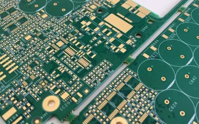
Rogers PCB materials are widely used in high-frequency, RF, microwave, radar, antenna, and high-speed electronic designs where standard FR4 PCB materials cannot provide stable enough dielectric performance or low enough signal loss. For engineers, Rogers materials are not selected because they are premium materials in general, but because they solve specific electrical problems related to insertion loss, dielectric consistency, impedance control, and thermal reliability.
At Highleap Electronics, we manufacture advanced boards using Rogers materials for high-frequency PCB and RF and microwave PCB applications, including mixed dielectric constructions that combine Rogers and FR4 in one stack-up. This guide explains what Rogers PCB materials are, how the major series differ, when mixed FR4 Rogers designs make sense, and what fabrication and assembly factors matter before release to production.
Request a Quote for Rogers PCB Fabrication
Table of Contents
- What Rogers PCB Materials Are and Why They Matter
- Main Rogers Material Families Used in PCB Design
- How to Choose the Right Rogers PCB Material
- Rogers vs FR4 Material Comparison
- When Mixed FR4 Rogers PCB Stackups Make Sense
- Rogers PCB Fabrication Considerations
- Rogers PCB Assembly and Handling Considerations
- Typical Applications of Rogers PCB Materials
- What to Send for Rogers PCB Manufacturing Review
- Rogers PCB Materials FAQ
What Rogers PCB Materials Are and Why They Matter
Rogers PCB materials are engineered laminates designed for electrical performance beyond the normal limits of standard FR4. They are commonly chosen when a design requires lower dielectric loss, tighter dielectric constant control, better thermal stability, or more predictable impedance behavior across high-frequency operation.
In practical engineering terms, Rogers materials matter when circuit performance depends on signal integrity more than on raw laminate cost. That includes RF front ends, microwave links, phased array systems, radar modules, high-frequency antennas, automotive sensors, test equipment, and certain mixed-signal high-speed designs.
The main reason engineers choose Rogers over standard FR4 is not simply better material. It is that Rogers laminates give more stable electrical performance at frequencies where FR4 becomes too lossy or too inconsistent for reliable design margins.
Main Rogers Material Families Used in PCB Design
Rogers offers multiple laminate families, and each one serves different design priorities. The most commonly referenced categories in PCB design include:
- RO4000 series: often selected when designers want a balance between RF performance, manufacturability, and cost. Common examples include RO4003C and RO4350B.
- RO3000 series: used in designs requiring very stable dielectric performance and low loss at higher frequencies. Common examples include RO3003, RO3006, and RO3010.
- RT duroid series: associated with very low-loss PTFE-based materials, often used in demanding microwave and antenna applications.
- TC series and related alternatives: used in cost-sensitive applications where designers still need improved RF performance compared to standard FR4.
These material groups are not interchangeable by default. The right choice depends on Dk target, loss budget, thermal needs, layer construction, and fabrication strategy.
| Material Family | Typical Strength | Common Use Case |
|---|---|---|
| RO4000 Series | Balanced cost and RF performance | General RF boards radar communication and mixed builds |
| RO3000 Series | Stable dielectric properties and low loss | Microwave filters amplifiers antennas and precision RF circuits |
| RT duroid Series | Very low loss at high frequency | Aerospace radar satellite and mmWave designs |
| TC and related systems | Cost optimization with improved RF behavior | Automotive radar and value-focused RF products |
How to Choose the Right Rogers PCB Material
Material selection should start from application requirements, not from brand familiarity alone. In real projects, Rogers PCB material selection usually depends on five main factors:
- Operating frequency: higher frequencies and tighter loss budgets usually require more stable and lower-loss laminates.
- Dielectric constant target: Dk affects line width, impedance, circuit size, and field behavior.
- Loss tangent: Df directly affects signal attenuation and insertion loss.
- Thermal and environmental conditions: power density, temperature cycling, moisture, and reliability expectations all matter.
- Cost and stack-up strategy: sometimes the correct answer is not full Rogers construction, but a mixed dielectric build that uses Rogers only where it adds clear value.
For example, if the design is a compact RF board with critical signal layers but non-critical power and control layers, a full Rogers stack-up may not be necessary. A mixed dielectric stack-up can often achieve the needed RF performance at lower cost.
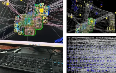
This is where early engineering review becomes important. Material choice should be made together with stack-up planning, impedance modeling, and process capability review rather than as a late procurement decision.
Rogers vs FR4 Material Comparison
Engineers often compare Rogers materials with FR4 because FR4 remains the default substrate for most standard PCBs. The difference is not that one is always better than the other. The real issue is whether FR4 can still meet the performance requirements of the design.
| Factor | Rogers Materials | FR4 |
|---|---|---|
| High-frequency loss | Lower and more stable | Higher and more variable |
| Dielectric consistency | Tighter control | Broader variation |
| Impedance predictability | Better for RF and microwave routing | Adequate for standard digital designs |
| Thermal reliability | Often better in demanding conditions | Good for general electronics |
| Material cost | Higher | Lower |
| Best fit | RF microwave radar antenna high-speed precision systems | General digital control and cost-sensitive boards |
In short, FR4 is usually the right choice for conventional electronics, while Rogers materials become worthwhile when the electrical penalty of FR4 is too large for the application.
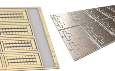
When Mixed FR4 Rogers PCB Stackups Make Sense
One of the highest-value strategies in RF PCB design is the mixed FR4 Rogers stack-up. This approach uses Rogers material only on the layers where low loss and dielectric stability are most important, while using FR4 on non-critical layers to control cost.
Mixed stack-ups make sense when:
- RF or microwave routing is limited to specific signal layers
- Control, power, or digital logic layers do not need premium RF material
- The design needs better performance than FR4 can provide but does not justify full Rogers construction
- The product is cost-sensitive and built in volume
However, mixed constructions also introduce manufacturing complexity. Lamination cycles, CTE behavior, bonding compatibility, dielectric thickness control, and drill registration all need closer control than in a conventional FR4 build. That is why hybrid stack-ups should always be reviewed with the fabricator before release.
Rogers PCB Fabrication Considerations
Rogers PCB fabrication is not just standard PCB processing with a more expensive laminate. It requires tighter attention to stack-up control, lamination parameters, drilling quality, copper treatment, and impedance consistency.
Important fabrication considerations include:
- Lamination control: hybrid builds may require more process attention than uniform FR4 stack-ups.
- Drilling and via quality: hole wall condition, smear control, and plating quality are critical for RF reliability and multilayer interconnection.
- Copper foil profile: rougher copper can increase conductor loss, especially at higher frequencies.
- Impedance control: RF lines need stable dielectric thickness and consistent etching performance.
- Material handling and storage: Rogers laminates should be handled carefully to maintain process consistency and prevent contamination.
This is why many customers choose to combine material selection review with early PCB fabrication planning instead of treating fabrication as a downstream purchasing task.
Rogers PCB Assembly and Handling Considerations
Material performance alone does not guarantee RF product success. Assembly also matters. A well-designed Rogers PCB can still underperform if soldering, connector installation, cleanliness, shielding integration, or rework control are poor.
Key assembly factors include:
- RF connector mounting quality: SMA, SMP, U.FL, and similar connectors must be assembled with good mechanical and electrical control.
- Flux and residue management: contamination near sensitive RF areas can affect long-term stability.
- Planarity and thermal control: high-density RF boards may include mixed package types and heat-sensitive devices.
- Shielding can placement: often important in communication, radar, and module-level products.
- X-ray and inspection strategy: especially important for BGAs, hidden joints, and dense RF modules.
For projects moving beyond bare board procurement, coordinated PCB assembly support can reduce the risk of performance loss between fabrication and final product build.
Typical Applications of Rogers PCB Materials
Rogers materials are used when signal performance, thermal stability, or RF reliability is too important to leave to standard laminate variation. Common applications include:
- 5G and wireless communication hardware
- Radar and mmWave systems
- RF filters, couplers, and power amplifiers
- Automotive radar and sensing modules
- Satellite and aerospace communication boards
- Precision test and measurement equipment
- Antenna and RF front-end modules
These products often require a balance between material performance, fabrication discipline, and cost optimization. That is why the best material choice is usually application-specific rather than brand-driven.
What to Send for Rogers PCB Manufacturing Review
If you want an accurate quotation and useful engineering feedback for a Rogers PCB, the design package should contain more than Gerber files alone. The manufacturer should be able to understand both the electrical intent and the stack-up strategy.
Recommended review package:
- Gerber files or ODB++ data
- Stack-up drawing with material callouts
- Target impedance requirements
- Board thickness and copper weight
- Any hybrid FR4 Rogers lamination notes
- Special drilling or back-drill requirements
- Assembly and RF connector requirements if applicable
Projects move faster when the material selection is reviewed together with layout, stack-up, and manufacturing constraints. If you need help validating a design before release, our team also supports manufacturing-oriented review at the design stage.
Rogers PCB Materials FAQ
What are Rogers PCB materials used for?
They are mainly used for RF, microwave, radar, antenna, and high-speed applications where standard FR4 does not provide stable enough dielectric performance or low enough loss.
Is Rogers better than FR4?
Not in every design. Rogers is usually better for demanding high-frequency performance, while FR4 remains the more economical choice for standard electronic products.
What is a mixed FR4 Rogers PCB?
It is a hybrid stack-up that uses Rogers on critical RF layers and FR4 on non-critical layers to balance performance and cost.
Why is Rogers PCB fabrication more difficult than FR4 fabrication?
Because mixed materials, tighter impedance expectations, copper profile effects, drilling quality, and lamination control all become more important in RF-grade manufacturing.
Can Rogers PCBs also be assembled at the factory?
Yes. For many RF boards and modules, fabrication and assembly should be coordinated closely to protect electrical performance and mechanical consistency.
Sabrina has over 18 years of experience in the PCB industry, with a strong background in CAM engineering and PCB file review. She supports PCB projects from prototype to volume production, focusing on manufacturability and process reliability. Her work helps engineering teams reduce production risk and achieve stable, high-quality PCB manufacturing results.

Related Articles
HF PCB Design and Manufacturing Rules
Essential HF PCB design and manufacturing guidelines. Maximize first pass success with precise impedance control, via back drilling, and thermal management.
HDI Blind Via PCB Cost Drivers Lamination Drill and Design
HDI blind via PCB cost from China factory with price breakdown lamination drilling via filling and cost optimization for Type I and Type II designs.
Quick Turn Ceramic PCB Fabrication Speed Cost and Lead Time
quick turn ceramic PCB lead time 5 to 10 days cost factors rush service pricing and fast fabrication options for urgent orders