
Back to blog
Metal Core PCB,MCPCB,Thermal Conductive PCB Material Guide

Metal Core Printed Circuit Boards (MCPCBs)
Hey, welcome to the interesting world of Metal Core Printed Circuit Boards (MCPCBs)! Ordinary PCBs use an FR4 dielectric core, but MCPCBs are different. They use a metal substrate, such as aluminum, copper, or iron alloys, as the middle layer. This special structure allows MCPCBs to dissipate the heat generated by high-power electronic components very well, so they are very important in places that require advanced thermal management!
In the following detailed explanation, we will talk about various metal core materials used in MCPCBs, compare their characteristics, and see what benefits they have. Also, we will talk about their manufacturing processes, specific applications, and how to choose the right MCPCBs for your project.
Understanding the Core Materials
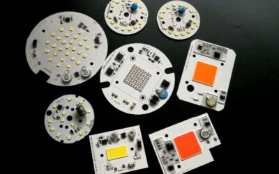
Aluminum Core MCPCB
Aluminum stands out as the most common core material used in MCPCBs due to its balance of thermal conductivity, cost-effectiveness, and manufacturability.
Properties
- Thermal Conductivity: 130 W/mK
- Coefficient of Thermal Expansion (CTE): 23 ppm/°C
- Density: 2.7 g/cm³
- Specific Heat Capacity: 0.9 J/g°C
Key Attributes
- Excellent heat dissipation
- Lightweight and recyclable
- Easy to fabricate and punch
- Cost-effective and widely available
Typical Thickness Range
- 0.5mm to 6mm (1mm to 2mm common)
Applications
Copper Core MCPCB
Copper offers unparalleled thermal conductivity, making it ideal for demanding thermal applications where heat dissipation is critical.
Properties
- Thermal Conductivity: 400 W/mK
- CTE: 17 ppm/°C
- Density: 8.9 g/cm³
- Specific Heat Capacity: 0.39 J/g°C
Benefits
- Exceptional thermal conductivity
- Compatible with standard PCB processes
- Can be used with high-temperature soldering
Typical Thickness Range
- 0.25mm to 4mm (0.5mm to 2mm common)
Applications
- High-power LED lighting
- RF power amplifiers
- Power modules
- High-density computer systems
Iron Alloy Core MCPCB
Iron alloys offer a balance between cost and thermal performance, providing a viable alternative to aluminum and copper.
Properties
- Thermal Conductivity: Up to 65 W/mK
- CTE: 10-15 ppm/°C
- Density: 7-8 g/cm³
- Specific Heat Capacity: 0.44-0.46 J/g°C
Benefits
- Improved thermal conductivity over aluminum
- More affordable than copper
- High strength at thin thicknesses
Typical Thickness Range
- 0.1mm to 3mm (0.2mm to 0.5mm common)
Applications
- LED lighting
- Industrial electronics
- Telecom systems
- Automotive
Comparing Metal Core PCB Materials
Comparing the key properties of the main metal core PCB materials:

Material Selection Guidelines
- Aluminum: Best for cost-driven applications requiring thermal conductivity above 130 W/mK.
- Copper: Ideal for applications where maximum heat dissipation is crucial.
- Iron Alloy: Suitable for weight and cost-constrained applications needing higher thermal performance than aluminum.

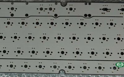
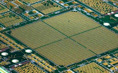
Metal Core PCB
Design Considerations for Metal Core PCBs (MCPCBs)
The performance and reliability of Metal Core PCBs hinge on careful consideration of several design factors:
Thermal Expansion
The coefficient of thermal expansion (CTE) represents the degree to which a material expands or contracts in response to temperature changes. In MCPCBs, mismatched CTEs between the metal core and other layers can lead to structural issues:
- Material Selection: Select materials with compatible CTEs to minimize stress between layers during thermal cycling.
- CTE Management: Employ thermal relief techniques and adjust layer thicknesses to alleviate stress.
- Lamination Process: Optimize the lamination process to bond the layers firmly, preventing delamination.
Thermal Conductivity
The primary function of MCPCBs is to efficiently dissipate heat, thus:
- Core Material: Choose metals like aluminum or copper for their high thermal conductivity.
- Insulating Layer: Use dielectric materials with high thermal conductivity to bridge the metal core and circuit layers.
- Copper Traces: Increase trace thickness to improve thermal dissipation while maintaining electrical integrity.
Electrical Design
The circuit design impacts both thermal management and electrical performance:
- Trace Width and Spacing: Optimize trace width and spacing based on current-carrying requirements to minimize resistance.
- Via Design: Utilize thermal vias to facilitate heat transfer between layers.
- Impedance Control: Ensure impedance matching in high-frequency applications to prevent signal degradation.
Mechanical Design
The mechanical properties of MCPCBs influence their structural stability and suitability for specific applications:
- Core Thickness: Choose an appropriate core thickness to balance heat dissipation with mechanical strength.
- Component Mounting: Consider the layout for Surface-Mount Technology (SMT) and Through-Hole Technology (THT) components, ensuring proper thermal and mechanical support.
- Board Outline: Factor in the PCB’s overall size and shape to ensure it fits within the product’s mechanical design constraints.
In summary, the effective design of MCPCBs requires a nuanced approach that harmonizes thermal, electrical, and mechanical properties, ensuring the PCB can meet the application’s performance, durability, and reliability requirements.
Cost-Effective Solutions for Metal PCBs in LED Manufacturing
As an LED electronic product manufacturer, reducing metal PCB costs is crucial for maintaining competitiveness while ensuring quality. Here are several strategies you could employ:
1. Material Optimization
Core Material Selection: Opt for aluminum over copper as it’s generally more cost-effective and sufficiently effective in heat dissipation for many LED applications.
Dielectric Layer: Use thermally conductive dielectric layers that offer the best heat transfer at a lower cost.
2. Design Optimization
Layer Count: Minimize the number of layers in the PCB design without compromising thermal and electrical performance.
Trace Optimization: Efficient trace routing reduces material usage. This includes minimizing trace length and width where possible.
Standardization: Design PCBs to use standard dimensions and features, reducing customization costs.
3. Manufacturing Efficiency
Panelization: Design the PCBs to optimize panel usage, maximizing the number of boards per panel.
Batch Production: Produce in larger batches to benefit from economies of scale in material purchase and manufacturing setup costs.
4. Supplier Management
Supplier Selection: Work with suppliers who specialize in metal core PCBs and have competitive pricing, potentially in regions with lower labor costs.
Long-Term Contracts: Negotiate long-term contracts to lock in favorable pricing and ensure a consistent supply chain.
5. Assembly Process
Automation: Automate assembly processes to reduce labor costs and increase throughput.
Surface Finish: Use cost-effective surface finishes like HASL instead of more expensive options like ENIG, provided it meets your product requirements.
6. Testing and Quality Control
Testing Reduction: Reduce the cost of quality control by optimizing testing procedures to catch defects early, reducing scrap and rework.
These strategies should help you achieve cost reductions in metal core PCBs while maintaining the performance needed for your LED products.
Conclusion
Metal core PCBs represent a significant advancement in PCB technology, providing enhanced thermal management, reliability and performance for modern electronic devices. As the demand for more efficient and compact electronics continues to grow, the role of MCPCBs will become increasingly important.
Their ability to efficiently dissipate heat and provide reliable electrical connections makes them indispensable in applications such as automotive, aerospace and LED lighting. As we continue to push the boundaries of technology, MCPCB will evolve to meet the growing needs of the electronics world. So whether it’s powering your stylish smartphone or the complex circuits driving your satellites, remember that MCPCBs are the backbone of the next generation of electronic devices, ensuring they perform optimally in any environment.
FQA
1.What distinguishes Metal Core PCBs (MCPCBs) from traditional FR4 PCBs?
Metal Core PCBs utilize a metal substrate, such as aluminum, copper, or iron alloys, as the middle layer, whereas traditional FR4 PCBs use an FR4 dielectric core. This unique structure enables MCPCBs to efficiently dissipate heat generated by high-power electronic components, making them vital in applications requiring advanced thermal management.
2.What are the key benefits of using Copper Core MCPCBs?
Copper Core MCPCBs offer exceptional thermal conductivity, with a thermal conductivity of 400 W/mK. This makes them ideal for demanding thermal applications where maximum heat dissipation is crucial, such as high-power LED lighting and RF power amplifiers.
3.How do material selection guidelines help in choosing the right MCPCBs for specific applications?
Material selection guidelines provide valuable insights into choosing the most suitable MCPCB for a particular application based on factors such as thermal conductivity, cost, and performance requirements. For example, aluminum MCPCBs are best for cost-driven applications requiring thermal conductivity above 130 W/mK, while copper MCPCBs excel in applications where maximum heat dissipation is paramount.
4.What design considerations are crucial for ensuring the performance and reliability of Metal Core PCBs?
Design considerations such as managing thermal expansion, optimizing thermal conductivity, ensuring proper electrical design, and considering mechanical properties are essential for maximizing the performance and reliability of Metal Core PCBs. These factors ensure that the PCB can effectively dissipate heat, maintain electrical integrity, and withstand mechanical stresses in its intended application.
5.What cost-effective strategies can LED electronic product manufacturers employ to reduce metal PCB costs?
LED electronic product manufacturers can implement various cost-effective strategies, including material optimization, design optimization, manufacturing efficiency improvements, supplier management, assembly process optimization, and testing and quality control enhancements. These strategies help reduce costs while maintaining the performance needed for LED products, ensuring competitiveness in the market.
PCB & PCBA Quick Quote
Related Articles
Understanding Aluminum Substrate PCB: Types and Advantages
The core technology of aluminum substrate PCB lies in the intermediate insulation layer material, which mainly serves the functions of bonding, insulation, and thermal conduction.
Characteristics and Applications of Black Core PCB Material
When it comes to using black core PCBs in your products, Highleap Electronic stands out as a trusted manufacturer known for delivering quality and reliability.
Key Considerations for Special PCB Manufacturing
Get unbeatable performance for your Special PCB. Our advanced manufacturing machines techniques and teams provide the highest quality PCBs.
Take a Quick Quote