
Back to blog
How to Test a Circuit Board?
How To Test A Circuit Board
When a circuit board ceases to function, pinpointing the issue requires a systematic approach to testing and troubleshooting. Here’s a detailed guide on how to test a circuit board that has stopped working, ensuring you can identify and rectify problems efficiently.
Start with a Visual Inspection
The first step in diagnosing a non-functioning circuit board is a thorough visual inspection. This non-invasive technique can reveal obvious faults that might be causing the problem.
- Look for Physical Damage: Examine the board for signs of burns, cracks, or component damage. Pay close attention to areas around power components and connectors.
- Inspect Solder Joints: Check for cold solder joints (appear dull or cracked) and solder bridges (accidental connections between pads).
- Identify Discoloration: Discoloration can indicate overheating components. This often occurs near resistors, capacitors, and integrated circuits (ICs).
A magnifying glass or a microscope can be invaluable during this step, allowing you to see details that are not visible to the naked eye.
Check the Power Module
A common culprit in circuit board failures is issues within the power module. Ensuring that the board is receiving and correctly distributing power is crucial.
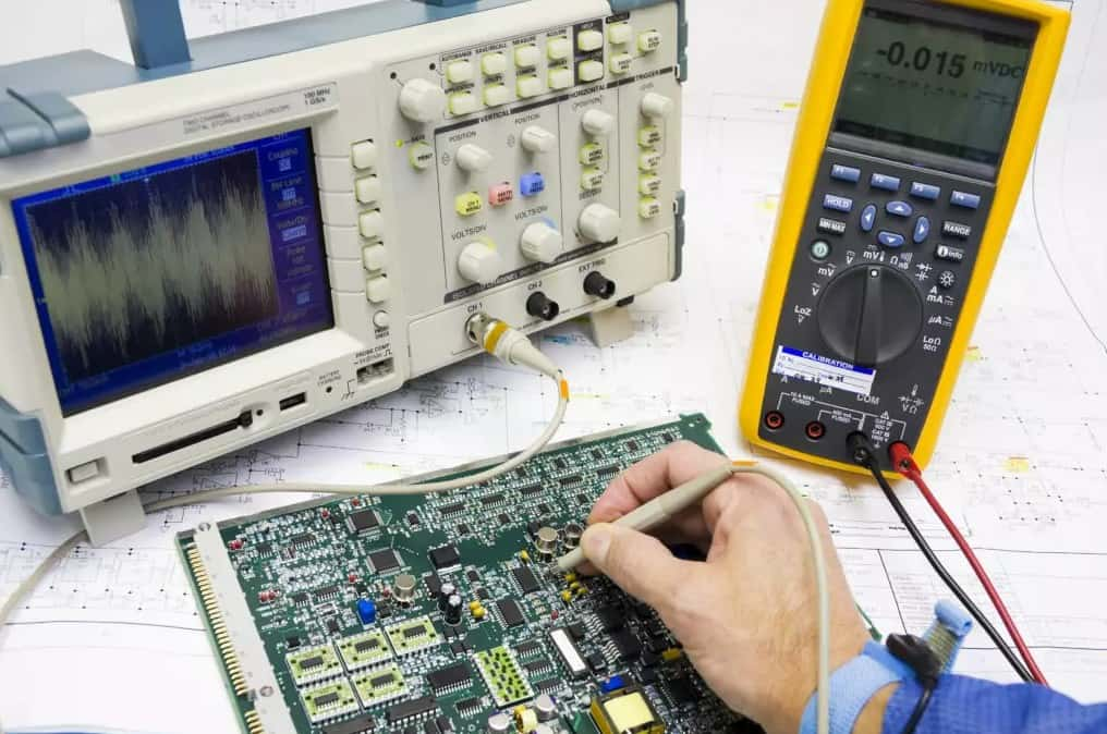
- Verify Power Supply: Use a multimeter to check the input voltage to the board to ensure it matches the required specifications. Also, check for any signs of wear or damage to power cables and connectors.
- Examine Voltage Regulators: Voltage regulators maintain constant voltage levels within the circuit. Test these components with a multimeter to verify they are outputting the correct voltages.
- Inspect Capacitors: Look for bulging or leaking capacitors, which can indicate failure. Capacitors are critical for filtering voltage and ensuring stable power supply to the board.
Check the Input/Output Ports
Faulty input/output (I/O) ports can prevent a circuit board from functioning properly by hindering communication with external devices.
- Continuity Test: Use a multimeter in continuity mode to test the connections between I/O ports and the rest of the circuit. Ensure there are no open circuits.
- Physical Inspection: Look for bent pins or damaged connectors that might be disrupting connections.
- Functional Test: If possible, connect known working devices to the I/O ports and verify communication.
Check Communication Ports
Communication ports, such as USB, Ethernet, or serial ports, are essential for data transfer. Issues with these ports can isolate the board, rendering it non-functional.
- Signal Integrity: Use an oscilloscope to check the integrity of signals passing through communication ports. Look for noise or distortion that could indicate a problem.
- Connectivity Test: Similar to I/O ports, check the continuity of connections from the communication ports to the main circuitry.
- Inspect for Physical Damage: Ensure the ports are not physically damaged and that there are no obstructions that could impede connection.
Strategic Design Enhancements
However, by integrating smart design strategies from the outset, PCBs can be optimized for easier troubleshooting and maintenance in the future. This approach not only streamlines the testing process but also enhances the overall efficiency of diagnosing and rectifying issues.
Integrating Testing Pads
One effective strategy for simplifying circuit board testing is incorporating testing pads dedicated to voltages and critical signals, including communication lines. These pads provide convenient access points for measurement tools, such as multimeters, without the risk of causing shorts by accidentally touching neighboring traces.
- Advantages: Testing pads enable quick and accurate measurements of essential signals and voltages, facilitating rapid identification of problems.
- Implementation: During the PCB design phase, allocate specific areas for testing pads, ensuring they are easily accessible and clearly labeled. This foresight prevents potential testing challenges and streamlines the troubleshooting process.
Adding Visual Indicators
The use of LEDs as visual indicators for power status, input/output activity, and communication signals is another practical design consideration that can significantly aid in troubleshooting.
- Benefits: LEDs provide immediate visual feedback on the operational status of various circuit components, allowing for quick identification of functional areas and pinpointing faults without extensive probing.
- Design Considerations: Incorporate LEDs strategically across the PCB to cover power supply circuits, major I/O ports, and communication interfaces. This not only aids in testing but also enhances the user experience by offering clear indications of device activity and status.
Leveraging PCB Design and Analysis Software
The complexity of modern PCB designs necessitates the use of advanced design and analysis software. Tools like OrCAD offer constraint management rules that ensure test points and visual indicators are optimally placed and remain unobstructed by other components.
- Software Features: OrCAD and similar PCB design software provide powerful features for laying out testing pads and LEDs, analyzing signal integrity, and managing design constraints to optimize the board for future troubleshooting.
- Efficiency Gains: By leveraging these software tools, designers can save significant time and reduce errors in the testing phase, ensuring that PCBs are both high-performing and maintainable.
PCB & PCBA quick quote
Related Articles
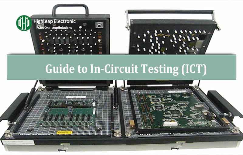
PCB Quality: The Definitive Guide to In-Circuit Testing (ICT)
[pac_divi_table_of_contents title="On this article" default_state="closed" included_headings="off|on|on|off|off|off" exclude_headings_by_class="on" active_link_highlight="on" level_markers_3="icons" title_container_padding="10px|15px|10px|15px|true|false"...

How to perform flying probe testing in PCB
[pac_divi_table_of_contents title="On this article" default_state="closed" included_headings="off|on|on|off|off|off" exclude_headings_by_class="on" active_link_highlight="on" level_markers_3="icons" title_container_padding="10px|15px|10px|15px|true|false"...

What Is Automated Optical Inspection (AOI)
[pac_divi_table_of_contents title="On this article" default_state="closed" included_headings="off|on|on|off|off|off" exclude_headings_by_class="on" active_link_highlight="on" level_markers_3="icons" title_container_padding="10px|15px|10px|15px|true|false"...

Highleap Electronic’s Approach to PCB Quality Assurance
[pac_divi_table_of_contents title="On this article" default_state="closed" included_headings="off|on|on|off|off|off" exclude_headings_by_class="on" active_link_highlight="on" level_markers_3="icons" title_container_padding="10px|15px|10px|15px|true|false"...
Take a Quick Quote