
Custom RF Cables and PCB Integration for Seamless Connectivity

What Are RF Cables?
RF Cables (Radio Frequency cables) are specialized interconnects designed to transmit signals across a wide range of radio frequencies. They are a critical part of modern communication and electronic systems, where low loss RF cables and precise RF cable assembly are essential for maintaining performance and reliability.
Key Characteristics and Roles of RF Cables
- Transmission of High-Frequency Signals
RF cables are engineered to carry signals within the RF spectrum, from a few megahertz (MHz) to several gigahertz (GHz), with options such as custom RF cables tailored to specific application requirements. - Wide Range of Applications
They are commonly used in telecommunications, aerospace, defense, and medical equipment, connecting devices like antennas, radios, and transmitters. In particular, RF coaxial cables for wireless communication are widely deployed to ensure seamless connectivity. - High-Frequency Signal Integrity
A primary advantage of RF cables is their ability to maintain signal integrity even in demanding high-frequency environments. Proper shielding and construction help minimize attenuation, ensuring strong and clear signal transmission. - Construction for Performance
The use of advanced materials, shielding techniques, and precision manufacturing ensures that RF cables deliver consistent electrical performance, especially in applications that demand low insertion loss and stable phase response. - Versatile Usage
RF cables are not limited to one industry. They are integral to broadcasting, data networks, satellite systems, and test equipment, where reliability and durability are crucial.
In summary, RF cables—whether standard or custom RF cable solutions—play a vital role in enabling reliable, high-performance connectivity across industries. Their proper selection and integration into electronic assemblies directly influence system efficiency and long-term reliability.

Cable Types and Constructions
The construction and types of RF cables vary significantly, each designed for specific applications and performance criteria:
- Coaxial Cables
- Inner Conductor: Central conductor surrounded by a dielectric insulator.
- Outer Conductor: Acts as a shield, typically made of metal.
- Frequency Range: Commonly used up to 6 GHz.
- Types:
- RG-174: Thin and flexible, suitable up to 3 GHz.
- RG-58: Low loss, effective up to 1 GHz.
- RG-8 and RG-213: Thick and designed for high power applications.
- Semi-Rigid: Features a solid conductor, usable up to 18 GHz.
- Twinaxial Cables
- Construction: Two inner conductors with twists to maintain balanced characteristics.
- Use: Ideal for data transmission, supporting speeds up to 10 Gbps.
- Triaxial Cables
- Design: Similar to coaxial cables but with an additional shield layer.
- Shielding: Provides very high noise immunity due to the extra shielding.
- Waveguides
- Structure: Hollow metal pipes guiding RF waves.
- Frequency Range: Used for frequencies over 18 GHz, offering low signal loss even up to 100 GHz.
- Leaky Feeder Cables
- Design: Coaxial cables with periodic slots in the shield.
- Function: Radiates the signal along the length of the cable, commonly used in indoor wireless systems distribution.
Each cable type serves a distinct role, catering to varying requirements in terms of frequency, power handling, and environmental conditions.
Contact us today to source the best RF cables and enhance your electronic systems!

Applications of RF Cables
RF cables find extensive use in various industries and applications due to their reliable signal transmission capabilities. Here are some key areas where RF cables are commonly employed:
Wireless Communications
- Antenna feeds for transmitting and receiving signals
- Connecting base stations to ensure seamless communication
- Distributed antenna systems for improved coverage and signal distribution
Wireless Networks
- Connecting routers, access points, and repeaters to establish wireless networks
- Structured cabling in buildings to provide network connectivity
- Data centers and server rooms for efficient data transmission
Broadcast TV/Radio
- Studio wiring and antenna feeds for broadcasting stations
- Portable equipment connections for on-the-go broadcasting
- Temporary outdoor setups for event broadcasting
Aerospace / Defense
- Airborne radar and avionics systems for aircraft communication and navigation
- Shipboard and vehicle communications for naval and land-based operations
- Missile guidance systems for accurate targeting
- Robotic systems control in unmanned aerial vehicles and ground-based vehicles
Medical Systems
- MRI and imaging equipment for high-resolution medical imaging
- Surgical device connections for precise control and monitoring during procedures
- Patient monitoring systems for real-time health monitoring
Test and Measurement
- Connecting test equipment like signal generators, oscilloscopes, and spectrum analyzers for accurate measurements
- Anechoic chamber wiring for controlled testing environments
Shielding in RF Cable Assemblies
Shielding in RF cable assemblies is a critical feature that ensures signal integrity and minimizes electromagnetic interference (EMI). It involves using a conductive layer, typically made of materials like copper or aluminum, surrounding the core of the cable. This conductive shield acts as a barrier, preventing external EMI from distorting the signal and stopping the RF signal within the cable from leaking out and affecting other devices.
Effective shielding is essential in environments with high levels of EMI, such as industrial settings, medical facilities, or areas with numerous electronic devices. The effectiveness of the shielding depends on factors like the material used, coverage area, and the cable’s design. Properly shielded cables ensure clear signal transmission, crucial for the reliability and accuracy of communication and data systems.
Environmental Factors Affecting RF Cables
RF cables are exposed to various environmental conditions that can affect their performance and durability. Understanding these factors is crucial for ensuring reliable signal transmission and maintaining the longevity of RF cable installations. Here are some key environmental factors to consider:
- Temperature
Extreme temperatures can impact the electrical properties and physical integrity of RF cables. High temperatures can cause signal loss, increased attenuation, and even insulation degradation. On the other hand, low temperatures can make cables more brittle, leading to increased susceptibility to damage or breakage. - Humidity and Moisture
Moisture and humidity can cause corrosion and oxidation of the cable’s conductive components, leading to signal degradation and increased resistance. It can also affect the dielectric properties of the cable, resulting in altered impedance and signal loss. In high-humidity environments, proper moisture sealing and cable insulation are essential to prevent these issues. - Exposure to Chemicals
RF cables installed in environments with exposure to chemicals, such as industrial facilities or laboratories, need to withstand potential chemical corrosion. Certain chemicals can degrade the cable’s insulation, shielding, or connectors, leading to signal interference, loss, or even complete cable failure. Choosing cables with chemical-resistant materials and proper cable management practices are important for maintaining performance in such environments. - Mechanical Stress
RF cables may experience mechanical stress due to factors like bending, flexing, or vibration. Excessive or improper bending can cause signal loss, increased attenuation, and even cable breakage. Vibration can loosen connectors or damage the cable structure, affecting signal integrity. Proper cable routing, strain relief, and cable protection measures are necessary to minimize mechanical stress. - Electromagnetic Interference (EMI)
RF cables can be susceptible to electromagnetic interference from nearby electrical equipment, power lines, or other RF sources. EMI can introduce unwanted noise or disrupt the desired signal, leading to poor signal quality. Proper cable shielding and grounding practices help minimize the impact of EMI and ensure reliable signal transmission.
By considering these environmental factors and implementing appropriate measures, such as selecting cables designed for specific environmental conditions, applying proper cable management techniques, and following industry best practices, the performance and durability of RF cables can be optimized, ensuring reliable signal transmission in various applications.

RF Cable Assembly and Installation
RF cable assembly and installation involve several key steps and considerations to ensure proper functionality and performance. Here are some important aspects:
Electronic Cable Assemblies: RF cable assemblies consist of cables and connectors. A wide variety of coaxial connectors, such as SMA, SSMA, TNC, N-Type, DIN, etc., are available. Precision-machined contacts ensure reliable signal transmission.
Attaching Connectors: Connectors can be attached to the cable using various techniques, including soldering, crimping, compression fittings, or specialized connection methods. The choice depends on the connector type and cable construction.
Routing and Securing: Care should be taken to route and secure the cables properly. Avoid kinking or excessive bending, and secure the cables along their path without over-tightening. Clamps, lacing, and conduits can be used for proper cable management. Leaving service loops at connections allows for future flexibility.
Avoiding Interference: To minimize interference, it is important to keep properly shielded cables and maintain proper separation between them. Using crossover patterns can help reduce coupling. Grounding and shield terminations should be done correctly to maintain signal integrity.
Weatherproofing: In outdoor or harsh environments, weatherproofing measures are necessary. Special jacketing materials can protect cables from moisture and environmental factors. Drip loops can be used to shed moisture away from the connection points, and sealing connections prevents moisture ingress.
Lightning Protection: Proper lightning protection is vital for outdoor RF installations. Grounding cables entering buildings helps dissipate lightning strikes. Lightning arrestors can be installed to divert and dissipate lightning energy. Surge suppressors can also be used on equipment to protect against transient voltage spikes.
By following these steps and considering these factors during RF cable assembly and installation, you can ensure proper functionality, performance, and protection of the RF system. It helps maintain signal integrity, minimize interference, and protect against environmental hazards and electrical surges.

Cable Testing
RF cable testing is a critical process to validate the performance and reliability of cables used in RF systems. Thorough testing ensures the cable meets electrical, mechanical, and environmental specifications before deployment.
When designing an RF system, the components like modules, ICs, connectors and cables are selected based on requirements. While focus is often on active components, care must be taken in procuring and testing passive interconnects like cables. They can make or break system performance.
Once a cable is procured, testing validates if it meets the required specifications for the application. Critical parameters like insertion loss, return loss, VSWR, shielding effectiveness, phase stability and power handling must be evaluated. This requires understanding various test methods, calibration techniques, measurements, tolerances and instrumentation.
Test Parameters and Methods
Insertion Loss: Measures signal attenuation through the cable over the operating frequency band using a vector network analyzer (VNA). A sweep generator drives the VNA. The cable under test (CUT) is connected between a directional coupler and the VNA test port. The loss versus frequency is recorded.
Return Loss: Verifies how well the cable is impedance matched to the connected devices. Poor matching causes signal reflections. Using a VNA, return loss is measured by calibrating out test setup errors and then terminating the CUT with a load. The return loss trace is observed across the band.
VSWR: Related to return loss, VSWR checks for any impedance discontinuities that cause reflections. A high VSWR indicates mismatch which degrades signals.
Shielding Effectiveness: Validates the cable shield’s ability to prevent interference from radiated external fields. Conducted using specialized test equipment that injects signals and measures penetration into the cable.
Propagation Delay: Measures signal propagation time through the cable. Important for applications requiring precise timing and synchronization. Obtained by measuring phase or time delay versus frequency.
Phase Stability: Assesses phase deviation of signals over temperature swings and mechanical handling. Improves system accuracy and calibration. Phase change is measured using a VNA while stressing the cable.
Power Handling: Tests if cable withstands specified RF power levels without damage or excessive heating. Applied using a signal generator and monitoring cable temperature and parameters.
Bend Radius: Cable is repeatedly bent around different radii and tested for degradation in electrical performance. Ensures flexibility for installation and use.
Environmental Testing: Subjects the cable to extreme temperatures, humidity, vibration, shock, corrosion etc. as per application needs using specialized chambers.
Mechanical Testing: Cable is subjected to crush, impact, twisting and pulling forces to verify robustness and durability.
Standards Compliance: Validates that the cable meets necessary electrical, mechanical, environmental and safety standards for the industry and application.
Test Equipment and Setup
Typical cable test instruments:
- Vector Network Analyzer (VNA): Measures insertion loss, return loss, VSWR, phase etc.
- Time Domain Reflectometer (TDR): Used for impedance measurements and fault location.
- Signal Generator, Power Meter: Generate test signals, measure power handling.
- Spectrum Analyzer: Checks spurious, harmonics, distortion.
- Network Analyzer: For measuring capacitance, inductance and other electrical parameters.
- Chambers: Provide temperature, humidity, vibration, corrosion etc. stress screening.
- Power Supplies, Amplifiers: Biasing, driving cables under test.
- Mechanical Fixtures: Apply bending, twisting, crushing and pulling forces.
Calibration using known standards removes systemic errors. Precise connectors, adapters and test cables are used to interface the CUT to test equipment. Automation increases speed and repeatability.
Thorough documentation and analysis of measurement results is key. Overall, rigorous test methodology is required to validate cable’s real-world performance. This ensures reliability across diverse operating conditions when installed.
1. Insertion Loss Testing
Insertion loss is the signal attenuation through a cable over frequency. It depends on cable length, construction, frequency, bends etc. IL directly reduces available signal power, so minimizing IL is desirable. Accurate IL data aids system design.
Insertion Loss Causes
Conductor Loss: Resistive loss in central conductor and shield. Increases with frequency due to skin effect. Lower for larger conductors.
Dielectric Loss: Loss tangent of insulating material causes attenuation, especially at high frequencies. Low-loss dielectrics like foamed PE help.
Leakage: Radiation loss from imperfect shielding. Better shield coverage improves leakage.
VSWR Loss: Mismatch at connectors or flexing causes some power to be reflected back rather than transmitted.
Connector Loss: Interfaces add discontinuity and contact resistance. High-quality connectors reduce this.
Bending Loss: Bends exacerbate radiation loss and jacketing compression. Larger bend radius gives lower loss.
Assembly Issues: Poor preparation and attachment adds contact resistance. Inconsistent assembly causes variances.
Insertion Loss Testing
Equipment
- Vector network analyzer with test cables
- Sweep generator, amplifier
- Directional couplers, attenuators
- Detectors and power sensors
- Calibration kits
Procedure
- Assemble test setup: generator, couplers, test cables, VNA
- Calibrate equipment, especially leads to device under test
- Connect cable under test between coupler through path and VNA
- Enable sweep tones and record insertion loss at VNA over frequency range
- Measure IL at multiple center frequencies and spans to cover full range
- Compare results with specs. Perform repeatability testing.
- Failure analysis on cables with excessive loss
- Document results for all samples to contqin
Insertion loss testing validates cable attenuation is within limits and stable over the required frequency range. Data aids in system design and performance estimation.
2. Return Loss Testing
Return loss (RL) indicates how well the cable is impedance matched to the devices it connects. Mismatches cause signal reflections which can degrade performance. RL is affected by connector attachment, cable prep and handling. Thus measuring RL is important to qualify assembled cables.
Return loss compares the power of the incident signal to the reflected power caused at discontinuities like connector interfaces. It is the ratio of reflected to incident power in dB. Higher return loss in dB indicates lower reflections and better matching.
A perfectly matched cable would have infinite return loss. But in practice values above 15 to 20dB are acceptable. Lower return loss indicates mismatch which causes signal reflections. This can interfere with transmitted signals causing data errors.
Poor return loss may require trimming cable lengths, re-assembling connectors, or replacing damaged cables. RL must be validated to ensure proper functioning in RF systems.
Test Methods
Popular options to measure cable return loss:
Vector Network Analyzer: Allows swept RL measurements over a frequency range. Directional couplers isolate incident and reflected signals. Modern VNAs provide calibrated, accurate broadband results.
Cable Analyzers: Dedicated test instruments with source, coupler and meter to measure RL at discrete frequencies or over a range. Some include time-domain reflectometry (TDR) capability.
Noise Figure Meters: Provide RL measurement capability along with noise figure. Quick go/no-go testing of acceptable RL.
Spectrum Analyzer: With tracking generator and coupler, can measure RL versus frequency. More setup work is required.
Reflectometers: Devices dedicated to reflectivity measurement using bridges and tuned receivers. Used for specific frequency bands.
Calibration
To remove errors due to test cables, connections and couplers, calibration is required before measuring the cable under test. Short, open, load, and through calibration standards are used to normalize the measurement plane. Modern VNAs have automated calibration routines for convenience.
Return Loss Measurement Steps
- Configure test equipment for return loss measurement. Connect components like coupler, generators, detectors.
- Perform calibration using proper short, open, load, thru standards.
- Connect the cable under test. Terminate far end in characteristic impedance.
- Enable test signals and observe return loss vs frequency. Adjust scale for good resolution.
- Return loss at any frequency can be read using markers. Plot minimum, maximum values.
- Compare results with specs. Repeat for both connectors.
- Identify any deviations and debug as needed by re-terminating, re-measuring or re-assembling.
- Document results. Pass/fail based on requirements.
Proper return loss testing quantifies cable assembly quality and Matching. It ensures optimal system performance and prevents field issues due to mismatches.
3. VSWR Testing
VSWR (voltage standing wave ratio) measures impedance mismatch in cables causing reflections. It is the ratio of maximum to minimum voltage in a standing wave due to the forward and reflected traveling waves.
VSWR indicates discontinuities arise from connector mismatches or variations in cable impedance. A perfectly matched line would have a VSWR of 1. Values up to 1.5 are generally acceptable.
Causes of High VSWR
- Poor cable trimming or stripping leading to impedance change
- Low quality or improper connector attachment
- Improper cable prep like nicked conductors or insufficient overlap
- Damage or bends altering cable impedance
- Contamination affecting connector interfaces
- Cable flexing causing dimensional changes
VSWR Measurement Techniques
- Vector Network Analyzer: Measures VSWR from impdance or return loss data. No accessories needed.
- Dedicated VSWR Meter: Directly displays VSWR. Directional coupler routes forward and reflected signals.
- Spectrum Analyzer: With tracking generator and coupler, VSWR can be derived from return loss.
- Slotted Line: Allows determining min/max voltage locations to calculate VSWR. Mostly obsolete today.
- Reflectometers: Simpler VSWR devices using bridge and detector. Limited accuracy.
Steps to Measure VSWR
- Prepare test setup with VSWR meter or VNA with coupler
- Perform instrument calibration as needed
- Connect cable under test, terminate far end in Z0
- Enable test signal and sweep desired frequency range
- Record VSWR at intervals or max/min over span
- Analyze results and compare to acceptable limits
- Retest after re-termination or reassembly if needed
- Document VSWR results for all samples
Good quality RF cables should have low, consistent VSWR across the operating band. VSWR testing finds any detuning issues before installation.
4. Phase Stability Testing
Phase stability indicates how well a RF cable maintains constant phase over environmental changes like temperature as well as mechanical handling like flexing and vibration. Better phase stability improves system accuracy and calibration.
Phase stability errors arise due to dimensional and dielectric constant changes over temperature as well as mechanical deformation changing electrical length. High performance cables use specialized materials and construction techniques to enhance phase stability.
Testing phase stability involves measuring phase or electrical length changes in cables while subjecting them to thermal or mechanical stress. The peak phase change quantifies stability.
Test Methodology
Equipment
- Thermal chamber capable of at least -40C to 85C operation
- Vibration table with variable frequency and amplitude
- Vector network analyzer to measure phase
- Phase-stable test cables, connectors
- Fixtures to hold and route cables
Procedure
- Measure phase response at room temperature as reference
- Ramp temperature over required range (e.g. -40C to 85C)
- Measure phase vs. temperature and record peak deviation
- Subject cable to vibration testing from 10 Hz to 2 kHz
- Assess phase variation vs. vibration frequency
- Repeat on multiple samples and document results
- Analyze if performance meets specifications
Improving Phase Stability
- High density polyethylene dielectric
- Silver plated conductors
- Compensated/balanced construction
- Bonded laminates
- Loose jacket for flexure tolerance
- Avoiding plasticizers
- Mitigating moisture penetration
Stringent phase stability testing validates cable performance for demanding applications including satellite communications, radar and calibration systems.
5. Cable Bend Testing
Cable bend testing evaluates the minimum bend radius a RF cable can tolerate without degrading electrical performance. Bend radius is based on cable diameter. Tighter bends increase radiation and jacket compression losses.
Bend testing involves repeatedly flexing cables around different mandrel diameters, and measuring parameters like insertion loss after each test. The smallest diameter with acceptable results determines the usable bend radius.
Bend Loss Mechanisms
- Jacket Compression: Braid gets pressed closer to conductor, changing impedance and increasing loss.
- Dielectric Stress: Insulator gets stressed, altering electrical characteristics
- Radiation Loss: Bends raise field strength allowing more energy to radiate outward
- Conductor Deformation: Central conductor gets stressed with tight bends
- Structural Damage: Extreme bending can break conductors or shields
- Metallic Creep: Long term bending induces metallic creep changing performance
Bend Testing Approach
- Use mandrels with different diameters, usually varying by 6 mm
- Wrap cable around mandrel for at least 90 degrees
- Perform a minimum of 10 bends for each smaller diameter
- Measure key parameters like return loss and insertion loss after each set
- Examine cable physically for any jacket damage or kinks
- Repeat the bend sequence until performance degrades
- The previous diameter with acceptable performance is noted as minimum bend radius
- Correlate results with manufacturer specifications
Bend testing cables before deployment reduces field failures and maintenance. Properly rated cables ensure flexibility for routing without degrading electrical performance.
6. Cable Power Handling Testing
Power handling quantifies the maximum RF power a cable can transmit without suffering damage or exceeding mandated temperature rises. Testing is vital for high power links. Excess power can destroy cables.
Power handling depends on cable construction, materials, diameter and cooling. Testing verifies ratings by transmitting RF energy at successively higher levels while monitoring cable condition.
Test Methodology
Equipment
- RF signal generator covering required frequency band
- Directional coupler, attenuator
- Power sensors to measure RF power
- Thermocouples or thermal camera to monitor temperature
- Calorimeter (optional) to precisely measure heating
Procedure
- Prepare test assembly with signal generator, coupler, power sensor and cable under test
- Start at low power levels around 1 watt
- Increment RF power in steps, allowing temperature to stabilize
- Monitor cable temperature along its length
- Go up to 50% higher than rated power handling
- Check for damage like melted dielectric
- Repeat at different duty cycles and frequencies
- The highest power sustained within limits determines power rating
Accurately establishing cable power handling avoids overspecifying cables for cost savings or dangerously underspecifying which damages systems.
Conclusion
Selecting the optimal RF cable is critical for high-frequency applications, but the variety of options can make the decision challenging. Evaluating key parameters such as frequency range, power level, and environmental conditions is essential to align the cable with application requirements. Partnering with reputable manufacturers who specialize in RF cable design and offer consistent manufacturing and rigorous testing is crucial. Quality materials and precision engineering ensure performance, reliability, and long-term value.
At Highleap Electronic, while we do not produce RF cables, we leverage our extensive network of trusted RF cable manufacturers to help our clients source high-quality, customized RF cables tailored to their specific needs. Whether you require cables with low insertion loss, excellent phase stability, or advanced shielding for challenging environments, we ensure that the right solutions are delivered. Additionally, as a leading provider of PCB manufacturing and assembly services, we offer seamless integration of RF cables into your electronic assemblies, ensuring top-notch quality and reliability throughout your product lifecycle.
Investing in quality RF cables may involve a higher upfront cost, but the long-term benefits are undeniable—superior electrical performance, reduced downtime, and enhanced system reliability. With RF systems powering an increasing array of applications, from wireless communication to satellite and radar systems, choosing the right cable and a dependable partner like Highleap Electronic ensures your systems operate at their full potential. Contact us today to discuss your RF cables and PCB assembly needs, and let us help bring your project to life with unparalleled expertise and service.
FAQ
1. What are the most common types of RF cables?
The most common RF cables include coaxial, twinaxial, triaxial, waveguides, and leaky feeder cables. Among these, RF coaxial cables are the most widely used in wireless communication, broadcasting, and test equipment because they offer stable impedance and good shielding. For specialized applications, custom RF cables can be designed to deliver low loss or enhanced phase stability.
2. How to choose RF cables for wireless communication?
When selecting RF coaxial cables for wireless communication, consider key factors such as frequency range, signal loss, shielding effectiveness, and connector type. For high-performance networks, low loss RF cables help maintain signal integrity over long distances. In complex systems, choosing a cable with robust shielding and proper RF cable assembly ensures reliable operation in high-interference environments.
3. What is the difference between coaxial and twinaxial RF cables?
Coaxial RF cables use a single central conductor surrounded by shielding, making them ideal for high-frequency applications and long-distance transmission. In contrast, twinaxial RF cables have two inner conductors twisted together, which provide better noise immunity and are often used for high-speed digital data transfer. The choice depends on whether you need low attenuation for RF signals or balanced transmission for data integrity.
4. How do environmental factors affect RF cable performance?
Temperature, humidity, chemical exposure, and mechanical stress can significantly affect the durability and performance of RF cables. For instance, high temperatures can increase attenuation, while moisture may degrade shielding. In harsh environments, custom RF cable solutions with weatherproof jackets, moisture sealing, or chemical-resistant materials help maintain long-term reliability. Proper routing and strain relief during RF cable assembly also minimize mechanical stress.
5. What tests are used to ensure RF cable quality?
RF cable testing is essential to validate performance before deployment. Common tests include insertion loss, return loss, VSWR, phase stability, shielding effectiveness, and power handling. For mission-critical systems, low loss RF cables are tested using a Vector Network Analyzer (VNA) to ensure they meet required specifications. Environmental and mechanical stress tests are also conducted to verify durability in real-world conditions.

Recommended Posts
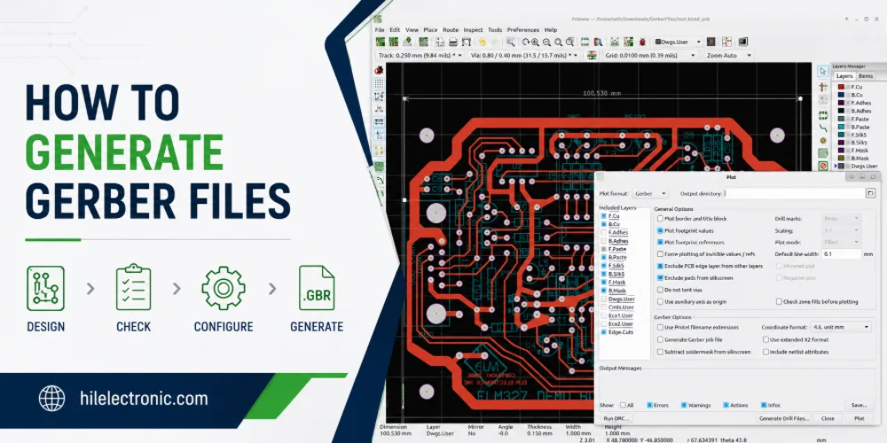
How to Generate Gerber Files for PCB Manufacturing
Figure 1. how to generate Gerber files image for Highleap...
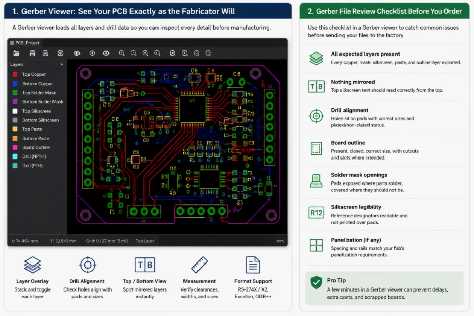
Gerber File Review Checklist: How to Check PCB Files Before You Order
Figure 1. Gerber file review catches missing layers, drill...
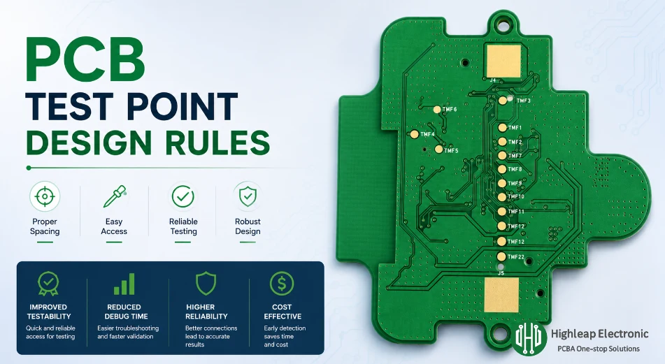
PCB Test Point Design Rules for Debug and ICT
Figure 1. PCB test point design rules help make debugging,...
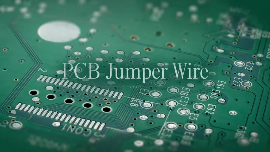
PCB Jumper Wire: Uses, Types, and Design Tips
Figure 1. PCB jumper wires are useful for prototypes and...
How to get a quote for PCBs
Let us run DFM/DFA analysis for you and get back to you with a report.
You can upload your files securely through our website.
We require the following information in order to give you a quote:
-
- Gerber, ODB++, or .pcb, spec.
- BOM list if you require assembly
- Quantity
- Turn time
In addition to PCB manufacturing, we offer a comprehensive range of electronic services, including PCB design, PCBA (Printed Circuit Board Assembly), and turnkey solutions. Whether you need help with prototyping, design verification, component sourcing, or mass production, we provide end-to-end support to ensure your project’s success. For PCBA services, please provide your BOM (Bill of Materials) and any specific assembly instructions. We also offer DFM/DFA analysis to optimize your designs for manufacturability and assembly, ensuring a smooth production process.