
From Physical-AI Prototype to Production: A PCB & PCBA Manufacturing Guide for Robotics Teams
A robot can walk, see, navigate or manipulate objects in a lab and still be far from production-ready. The difficult transition is turning a working electronics prototype into PCB assemblies that can be sourced, manufactured, inspected and tested with consistent results.
This article focuses on manufacturability and production readiness rather than a specific robot's proprietary hardware.
The problem is no longer “Can the robot work?” — it is “Can we build it again?”
Physical AI is pushing more intelligence into real machines: service robots, humanoids, AMRs, robotic arms, inspection systems, smart actuators and small research platforms. Once the software and mechanical systems are functional, electronics manufacturing becomes one of the key constraints on repeatability.
A lab prototype is usually optimized for learning quickly. Production hardware is optimized for something different: repeatable fabrication, controlled assembly, stable component supply, inspectability, testability and lifecycle support.
That difference is why a prototype can pass a bench test while a later build shows inconsistent yield, or why a pilot build can be delayed by one unavailable IC, one hard-to-inspect package or one undefined test requirement.
Related: the physical-AI trend
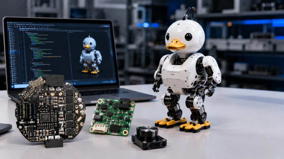
Our recently published Microduck physical-AI article looks at the software-to-hardware story behind a current robotics platform.
This guide moves one step closer to a purchasing decision: how a robotics team should prepare its PCB/PCBA package for prototype builds, NPI and production.
Prototype, NPI, pilot and volume builds solve different problems
One common mistake is treating every build as “the same PCB, just a different quantity.” In practice, the engineering objective changes as the project matures.
The manufacturing package determines how accurately your project can be reviewed
A quotation is only as reliable as the manufacturing data behind it. Missing or conflicting files create assumptions, and those assumptions create risk once parts are purchased or production begins.
Have the files but not sure whether the package is complete?
Send the available Gerber or ODB++ files, BOM and assembly data first. Highleap can review the manufacturing package and identify information that needs clarification before the build is released.
Manufacturability review should happen before an expensive build
DFM is not a replacement for electrical design verification. Its purpose is to identify features that may be electrically valid but difficult, expensive or unstable to manufacture.
For robotics hardware, the review often crosses several disciplines because the same board may combine fine-pitch logic, high-current power, connectors, sensors and mechanically stressed components.
Fabrication DFM
Trace/space, annular ring, drill-to-copper, via structure, copper balance, board thickness, stack-up and impedance feasibility.
Assembly DFA
Footprints, polarity, component spacing, paste apertures, thermal mass, board edge clearance, panelization and rework access.
Design for Test
Test points, programming access, fixture access, debug connectors and measurable pass/fail criteria.
Mechanical review
Connector forces, heavy components, mounting holes, cable direction, strain, enclosure clearance and vibration-sensitive parts.

Where IPC standards fit
IPC describes DFM as an important product-development activity, and its design standards include IPC-2221 for generic printed-board design. As of August 2026, IPC's published revision information lists IPC-2221C as the current generic design revision. The actual fabrication and assembly requirements for a project still need to follow the customer drawing, procurement specification and applicable product requirements.
Choose PCB technology because the robot needs it — not because it sounds advanced
Robotics electronics can use standard multilayer FR-4, HDI, heavy copper, flex, rigid-flex or specialty materials depending on the actual electrical and mechanical requirements. None of these technologies should be treated as a default for every robot.
Layer stack-up and return paths
High-speed compute, camera links, memory interfaces and communications may require controlled impedance and disciplined reference planes. The stack-up should be agreed upon before routing is finalized when impedance is performance-critical.
Current and thermal requirements
Motor-control or power-distribution boards may need wider copper features, heavier copper, thermal vias or other thermal measures. Copper weight and allowable temperature rise should be selected based on the actual current and thermal environment.
HDI only where density justifies it
Microvias, blind/buried vias and via-in-pad can help dense processor or BGA designs, but they add fabrication complexity and cost. Use them when escape routing, form factor or signal constraints require them.
Flex and rigid-flex for moving interconnects
Robots often have constrained moving joints and cable paths. Flex or rigid-flex may reduce connector count or packaging volume, but bend radius, dynamic flex life and stack construction must be defined for the application.
Highleap provides PCB fabrication together with assembly, which can reduce coordination gaps between bare-board manufacturing decisions and downstream component assembly. See PCB fabrication capabilities or the dedicated robot PCB manufacturing page.
A practical PCBA flow for robotics hardware
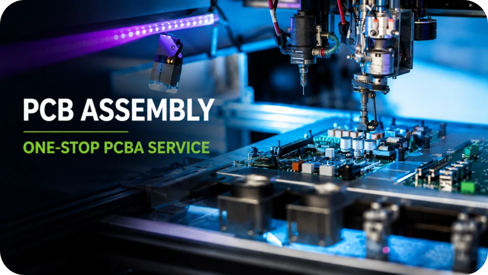
The exact route depends on board design and component mix, but a controlled PCBA build typically includes material verification, solder-paste printing, component placement, soldering, inspection and project-specific testing.
Fine-pitch logic and hidden joints
BGAs, QFNs and dense processor modules may require process controls and inspection methods appropriate to hidden solder joints. X-ray inspection is useful when potential defects cannot be evaluated visually, but the inspection plan should match the package type and risk.
Large connectors and mixed thermal mass
Robotics boards often combine small logic parts with connectors, inductors and power devices. Paste design, thermal profile, selective soldering or hand/fixture operations may need to account for the mixed thermal mass.
The BOM can stop a robot project before the assembly line does
Even a technically sound PCB layout does not solve component availability. For NPI and production, the BOM should be reviewed as a manufacturing document, not just an export from schematic software.
Use manufacturer part numbers
Generic descriptions such as “10 µF capacitor” are not enough for controlled purchasing. The BOM should identify the approved manufacturer and exact part number where performance or fit matters.
Define alternates deliberately
A substitute should not be approved simply because the package fits. Voltage, tolerance, temperature range, ESR, timing, firmware compatibility and qualification requirements can matter.
Manage lifecycle before ramp
Check for obsolescence, end-of-life status, long lead times and allocation risks before moving from a pilot build to production. A late BOM change can require requalification or firmware changes.
If sourcing is part of the quote, send the BOM early
Highleap's PCB assembly service includes component sourcing. Providing manufacturer part numbers, approved alternatives and forecast quantities allows sourcing risks to be reviewed before committing to a production schedule.
Do not use “tested” as a vague requirement
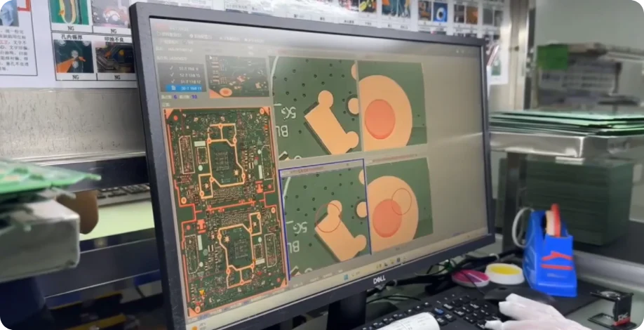
Inspection and testing solve different problems. AOI can identify visible assembly conditions; X-ray can help evaluate hidden joints; electrical testing can check selected nets or electrical conditions; functional testing can verify behavior under defined conditions. No single method verifies every aspect of a complex robot PCBA.
| Method | Useful for | Important limitation |
|---|---|---|
| SPI | Monitoring solder-paste deposition before component placement. | It does not prove the final solder joint or functional performance. |
| AOI | Checking visible placement, polarity and solder-related conditions. | Hidden joints beneath packages cannot be fully assessed visually. |
| X-ray | Inspecting hidden solder structures such as many BGA/QFN conditions. | Interpretation and acceptance criteria still need to be defined. |
| ICT / flying probe | Checking selected nets, components or electrical conditions where access and test development support it. | Coverage depends on design-for-test, fixture/probe access and the test program. |
| Functional test | Verifying board behavior using project-defined inputs, outputs, firmware and pass/fail limits. | A vague “power-on test” is not the same as a documented functional test procedure. |
Current assembly standards: specify the standard, revision and class
IPC published the J revisions of J-STD-001 and IPC-A-610 in 2024. J-STD-001 addresses soldered electrical/electronic assembly requirements and process controls; IPC-A-610 provides post-assembly acceptance criteria. As of August 2026, IPC's revision information lists J-STD-001J and IPC-A-610J.
Do not assume that every robotics product automatically requires the same IPC class. The project should define the applicable standard, revision, class, customer drawing requirements and any sector-specific requirements before production.
Cost reduction should remove unnecessary complexity, not manufacturing margin
The cheapest quotation is not always the lowest production cost. Robotics programs can lose more through repeated redesign, excess scrap, line stoppages or component shortages than they save through a small unit-price reduction.
Reduce unnecessary PCB complexity
Do not use HDI, sequential lamination, specialty materials, unusually tight tolerances or heavy copper unless the electrical, thermal or mechanical requirement justifies it.
Design for assembly margin
A footprint that only works at the process limit may create yield sensitivity. Stable spacing, appropriate land patterns and reasonable panelization can be more valuable than squeezing the final millimeter from the board.
Make test access intentional
Adding accessible test points during layout is usually easier than creating workarounds after the product has entered NPI.
Freeze revisions before buying volume
Component purchasing and PCB fabrication should reference controlled revisions. Late engineering changes can strand components, bare boards, stencils or test fixtures.
For robotics, the supplier has to manage the interfaces between processes
Robot electronics often span bare PCB fabrication, component sourcing, SMT, through-hole assembly, programming, testing, coating and final electromechanical integration. Splitting every step across unrelated suppliers can work, but it increases the number of interfaces the engineering team has to manage.
Questions worth asking before placing the order
- Who reviews DFM and assembly questions before release?
- How are BOM shortages and substitutions communicated?
- Which inspection methods are appropriate for the component package mix?
- How will first-article or pilot issues be documented and resolved?
- Can the supplier support programming and functional testing when procedures are provided?
- How are PCB, BOM, firmware and assembly revisions controlled?
- Can the same partner support prototype, pilot and subsequent production?
Highleap's relevant service scope
Highleap's published PCB assembly services include PCB manufacturing coordination, component sourcing, SMT, through-hole assembly, PCBA testing, IC programming, conformal coating, potting and finished-product assembly options.
For robotics teams, that creates a path from bare PCB and PCBA through additional integration steps when the project requires them.
What to send Highleap for a robotics PCB / PCBA quotation
If your design is already at the quotation stage, sending a complete package reduces clarification cycles and helps the manufacturing team understand the actual build rather than make assumptions from Gerber files alone.
Build the next robot as a repeatable product, not just a successful prototype.
Highleap Electronics provides PCB fabrication, component sourcing and PCB assembly support for robotics, embedded control and other electronics projects from prototype builds through production. Send your current manufacturing package for review and quotation.
Manufacturing requirements, testing scope and applicable industry standards should always be defined for the specific product and customer requirements.
Questions robotics teams ask before PCB assembly
What files should I send for a robot PCB assembly quote?
For an accurate PCBA review, send PCB fabrication data, the BOM with manufacturer part numbers, pick-and-place data, assembly drawings and the required quantities. If programming, functional testing, coating or other secondary processes are required, include those requirements as early as possible.
My prototype works. Can I go directly to volume production?
A working prototype proves important electrical and software assumptions, but it does not automatically prove manufacturing repeatability. An NPI or pilot build is useful for finding DFM, sourcing, assembly, documentation, inspection and test issues before committing to larger material purchases.
Do all robotics PCBs need HDI or heavy copper?
No. HDI, heavy copper, flex, rigid-flex and specialty materials should be selected based on actual requirements for routing density, current capacity, thermal performance, size, signal integrity and mechanical constraints. Using advanced PCB technology without a design need can add unnecessary cost and process complexity.
Is AOI enough to test a robotics PCBA?
No. AOI is an inspection method for visible assembly conditions. Depending on the design and risk profile, the manufacturing plan may also use X-ray, electrical testing, programming and functional testing. The correct combination depends on package types, test access and product requirements.
Which IPC class should a robot PCB assembly use?
There is no single IPC class that automatically applies to every robot. The class and applicable standards should be defined by the customer, product performance requirements, risk, contractual requirements and any sector-specific rules.
How to get a quote for PCBs
Let’s run DFM/DFA analysis for you and get back to you with a report. You can upload your files securely through our website. We require the following information in order to give you a quote:
-
- Gerber, ODB++, or .pcb, spec.
- BOM list if you require assembly
- Quantity
- Turn time
For PCBA services, please provide your BOM (Bill of Materials) and any specific assembly instructions. We also offer DFM/DFA analysis to optimize your designs for manufacturability and assembly, ensuring a smooth production process.