
Back to blog
Leveraging IPC-2221 for Optimal PCB Design
IPC-2221, developed by the Institute of Printed Circuits (IPC), now known as the Association Connecting Electronics Industries, is a standard that provides guidelines for designing reliable and manufacturable printed circuit boards (PCBs).
Covering a broad range of topics, including materials, board size and shape, component placement, trace and space widths, via design, and thermal considerations, IPC-2221 ensures that PCB designs are both reliable and manufacturable.
Materials Considerations in IPC-2221
In PCB design, selecting the right materials is crucial for meeting cost, reliability, and performance requirements. IPC-2221 provides valuable guidance on material selection, covering various aspects to consider:
Copper Thickness: IPC-2221 advises on the minimum copper thickness needed based on the board’s purpose and environmental conditions. Copper thickness directly impacts the board’s current-carrying capacity and thermal performance.
Substrate Materials: The standard recommends materials such as FR-4, polyimide, and ceramic based on their electrical, mechanical, and thermal properties. FR-4 is commonly used for its affordability and versatility, while polyimide offers excellent thermal stability and chemical resistance.
Solder Mask Materials: IPC-2221 provides criteria for selecting solder mask materials with thermal stability, chemical resistance, and adhesion properties. These criteria ensure that the solder mask can withstand the manufacturing process and provide reliable protection for the copper traces.
Surface Finish: IPC-2221 offers options like ENIG (Electroless Nickel Immersion Gold), HASL (Hot Air Solder Leveling), and OSP (Organic Solderability Preservatives) based on usage and material compatibility. Surface finish selection is crucial for ensuring good solderability and corrosion resistance.
Conductive Trace Materials: IPC-2221 suggests copper, gold, or silver based on their electrical performance and cost. Copper is widely used due to its excellent conductivity and affordability, while gold and silver are preferred for their superior conductivity in specific applications.
Dielectric Materials: IPC-2221 recommends dielectric materials based on their electrical, thermal, and mechanical properties. For high-speed and RF applications, dielectric constant and loss tangent are critical considerations to maintain signal integrity and minimize losses.
Environmental Considerations: IPC-2221 guides on selecting materials suitable for specific operating conditions, such as high temperature or humidity. Environmental considerations are crucial for ensuring the reliability and longevity of the PCB in its intended application environment.
By adhering to these guidelines, PCB designers can ensure that their designs meet performance, reliability, cost, and environmental requirements. Proper material selection is key to achieving a successful PCB design that meets the needs of its intended application.
Component Placement Guidelines in IPC-2221
In PCB design, proper component placement is crucial for ensuring electrical performance, manufacturability, and reliability. IPC-2221 provides detailed guidelines for component placement, covering various aspects:
Orientation: IPC-2221 instructs designers on how to position components to minimize electrical path length and prevent interference between nearby components. Proper component orientation can improve signal integrity and reduce electromagnetic interference (EMI).
Clearance and Spacing: IPC-2221 specifies the appropriate distance between components based on their size and intended use. Adequate clearance and spacing help prevent electrical shorts and ensure proper mounting and soldering of components, enhancing the reliability of the PCB.
Trace Routing: IPC-2221 offers instructions on how to route traces between components to minimize interference and maintain optimal electrical performance. Keeping trace lengths as short as possible helps reduce signal degradation and EMI.
Thermal Considerations: IPC-2221 recommends placing components to optimize thermal performance, ensuring that heat-generating components are isolated from sensitive ones. Proper thermal management can prevent overheating and improve the overall reliability of the PCB.
By following IPC-2221 guidelines for component placement, PCB designers can ensure that their designs meet performance, manufacturability, and reliability requirements. Proper component placement is essential for optimizing electrical performance, minimizing interference, and enhancing the overall reliability of the PCB.
Board Size and Shape Guidelines in IPC-2221
The IPC-2221 standard provides comprehensive guidelines for designing printed circuit boards (PCBs) with various sizes and shapes, ensuring structural integrity, manufacturability, and reliability. Here are key considerations covered by IPC-2221 regarding board size and shape:
Aspect Ratio: IPC-2221 offers recommendations for aspect ratios based on board size and use. The aspect ratio is the ratio of the board thickness to the smallest feature size, such as trace width or hole diameter. Proper aspect ratio selection is crucial for ensuring the board’s mechanical stability and manufacturability.
Board Edge Design: IPC-2221 guidelines help design board edges to minimize the risk of harm during handling and assembly. The standard specifies minimum edge clearance requirements and suggests adding chamfers or bevels to prevent sharp corners, which can improve both safety and manufacturability.
Board Size Limitations: IPC-2221 guides designers on how to design PCBs of varying sizes, considering manufacturing process limitations and the board’s intended purpose. This includes setting minimum and maximum dimensions for the board, as well as considering panelization and manufacturing tolerances to ensure the design is practical and feasible.
Placement of Mounting Holes: IPC-2221 dictates where to place mounting holes on a board, considering factors such as the minimum distance from the board edge and spacing between holes. Proper mounting hole placement is critical for ensuring the board remains structurally sound and securely mounted in its intended application.
PCB Thickness: IPC-2221 offers guidance on selecting the appropriate thickness for a board, considering its intended use and environmental factors. The standard outlines the smallest and largest thickness allowed, taking into account manufacturing processes such as drilling and plating.
By adhering to IPC-2221 guidelines for board size and shape, PCB designers can ensure that their designs are structurally robust, manufacturable, and reliable, meeting industry standards and best practices.
Trace and Space Guidelines in IPC-2221
IPC-2221 provides comprehensive guidelines for trace and space design in PCBs to ensure optimal electrical performance, reliability, and manufacturability. Here are key aspects covered by IPC-2221 regarding trace and space:
Trace Width: IPC-2221 assists in selecting trace widths based on the current-carrying capacity and manufacturing processes. Wider traces are necessary for carrying more current, while narrower traces can be used for signals with lower current requirements.
Space Width: IPC-2221 recommends space widths to prevent electrical shorts and ensure proper soldering. Sufficient space between traces is crucial for avoiding unintended electrical connections and ensuring reliable solder joints.
Impedance Control: IPC-2221 provides instructions for impedance control, which involves maintaining consistent trace width and spacing to achieve a specific impedance value. This is particularly important for high-speed and RF applications to ensure signal integrity and minimize signal distortion.
Differential Pair Routing: IPC-2221 directs on routing differential pairs, which are two traces that carry equal and opposite signals. Maintaining uniform impedance and minimizing interference between neighboring traces are critical for ensuring signal integrity in differential pairs.
Via Spacing: IPC-2221 offers recommendations for via spacing to prevent shorts and allow for proper plating. Vias are used to connect traces on different layers of the PCB, and proper spacing between vias is essential to avoid electrical shorts and ensure reliable connections.
By following IPC-2221 guidelines for trace and space design, PCB designers can ensure that their designs meet the necessary electrical performance and reliability standards, as well as manufacturability requirements. Proper trace width and spacing selections, impedance control, and differential pair routing are all factors that can improve the PCB’s electrical performance and reliability.
Via Design Guidelines in IPC-2221
IPC-2221 advises on designing vias for electrical performance, reliability, and manufacturability:
- Via size: Guiding on choosing sizes based on purpose and manufacturing process.
- Via spacing: Recommending spacing for preventing shorts and ensuring proper plating.
- Via placement: Specifying positions for minimal path length and interference prevention.
- Via types: Recommending types based on design requirements, such as blind, buried, or through-hole.
- Via plating: Instructing on plating thickness and type based on purpose and manufacturing process.
Thermal Considerations in IPC-2221
IPC-2221 offers guidance on managing heat dissipation and preventing thermal damage:
- Thermal conductivity: Recommending materials with suitable thermal conductivity.
- Thermal relief: Providing instructions for patterns around copper pads for easier soldering and heat dissipation.
- Copper weight: Guiding on selecting copper amounts for efficient heat dispersion.
- Thermal vias: Advising on creating vias for heat dissipation from heat-generating components.
- Thermal management: Instructing on creating management systems like heat sinks and fans for heat dissipation.
IPC-2221 Implementation and Benefits
Implementing IPC-2221 guidelines in PCB design offers numerous benefits for designers, manufacturers, and end-users:
- Improved Manufacturability: By adhering to IPC-2221 guidelines, designers can create PCB designs that are easier to manufacture, resulting in fewer errors and reduced rework. This leads to smoother production processes and improved overall efficiency.
- Increased Reliability: IPC-2221 guidelines ensure that PCB designs meet the required performance and reliability standards. This helps prevent failures and increases the lifespan of the PCB, leading to more reliable electronic products.
- Cost Savings: Following IPC-2221 guidelines can lead to cost savings in manufacturing. By reducing the need for rework and improving yield, manufacturers can lower their production costs and improve their bottom line.
- Consistency: IPC-2221 is a set of standardized guidelines for PCB design. By following these guidelines, designers and manufacturers can maintain consistent standards across various suppliers and vendors, resulting in better PCB design and manufacturing.
- Environmental Benefits: IPC-2221 guidelines also have environmental benefits. By reducing the use of hazardous materials and improving the environmental impact of PCB designs, designers can contribute to a more sustainable manufacturing process.
Overall, implementing IPC-2221 guidelines in PCB design can lead to improved manufacturability, increased reliability, cost savings, consistency, and environmental benefits. These guidelines are widely recognized and accepted in the PCB design industry and can help designers create high-quality, reliable, and cost-effective PCBs.
Conclusion
IPC-2221 is an essential standard for designing PCBs, ensuring reliability, manufacturability, and performance. Following its guidelines can lead to enhanced production, reliability, cost-effectiveness, and environmentally friendly operations for manufacturers. Adhering to IPC-2221 is crucial for creating designs that meet performance specifications, are easy to manufacture, and are cost-effective without compromising on reliability or environmental impact.
Looking for a reliable PCB and PCBA manufacturer? Our company offers high-quality PCB and PCBA services, adhering to IPC-2221 standards. Contact us today to learn more about how we can help with your PCB and PCBA needs.
PCB & PCBA Quick Quote
Related Articles
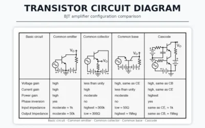
Transistor Circuit Diagram: Symbols, Reading, and Build
Learn how to read a transistor circuit diagram, recognize BJT and MOSFET symbols, and convert a schematic into a practical PCB design.
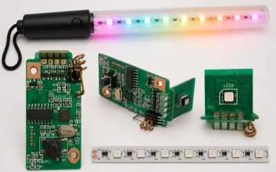
LED Placement and Orientation on PCB: Marking Guide
Learn how to mark LED polarity and placement on a PCB so assembly teams avoid reversed parts, dark boards, and preventable rework.
PCB Jumper Wire: Uses, Types, and Design Tips
Understand when to use a PCB jumper wire, how it differs from zero-ohm links, and what design rules prevent unreliable board rework.