
PCBA First Article Inspection Saves You Money

Table of Contents
When embarking on a new printed circuit board assembly project, the First Article Inspection (FAI) acts as the definitive gateway between engineering design and mass production. It is not merely a visual glance; it is a systematic, data-driven validation of the entire manufacturing process. This guide is written for hardware engineers and project managers who need to understand exactly what a competent manufacturer verifies during FAI, and why the approval phase is universally time-sensitive.
1. When Is a Rigorous PCBA FAI Mandatory?
1.1 Design Triggers for Comprehensive Inspection
While every new batch requires an FAI, the depth of the inspection scales with the complexity of the board. A structured FAI is absolutely critical and cannot be rushed under the following conditions:
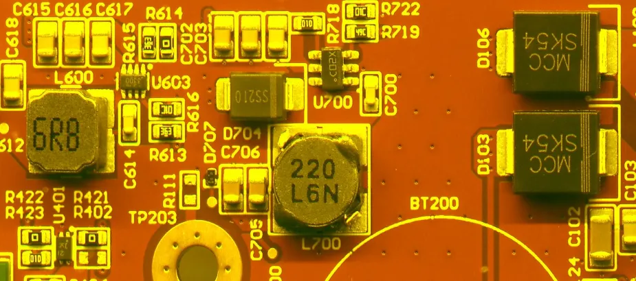
- High-Density Interconnects: Boards featuring BGAs, CSPs, or QFNs with pitches of 0.4 mm or finer, where visual inspection is impossible and 3D X-Ray (AXI) is required.
- Complex Component Layouts: Designs such as high-end custom mechanical keyboard PCBs, which require precise alignment of hotswap sockets, RGB LEDs, and diodes across a large surface area.
- Strict Regulatory Requirements: Medical, automotive, or aerospace assemblies where IPC-A-610 Class 3 compliance must be documented for every solder joint.
- BOM Changes: Any run where an alternative component (cross-reference part) has been introduced due to supply chain shortages.
2. What the FAI Process Mainly Confirms
2.1 BOM Verification and Component Validation
The foundation of FAI is ensuring the physical board matches the digital Bill of Materials perfectly. At Highleap Electronic, this goes beyond checking component values. We verify:
- Manufacturer Part Number (MPN): Confirming the exact brand and series, especially for critical capacitors (ESR values) and precise resistors (0.1% tolerance).
- Footprint Match: Ensuring the physical component fits the land pattern without overhang or insufficient heel fillets.
2.2 Placement Accuracy and Orientation
Modern SMT (Surface Mount Technology) machines are fast, but programming errors can occur. FAI utilizes high-resolution AOI (Automated Optical Inspection) to confirm:
- X/Y Coordinates: Components are perfectly centered on their pads to prevent tombstoning during reflow.
- Polarity: Strict verification of pin 1 indicators on ICs, cathode marks on diodes, and polarity on electrolytic capacitors. A single reversed IC can destroy the entire board upon power-up.
2.3 Soldering Quality and Defect Analysis
The physical connection is scrutinized against IPC-A-610 standards. We look for:
- Solder Volume: Checking for insufficient solder (weak joints) or excessive solder (potential bridging).
- Hidden Joints: Utilizing X-Ray inspection to check for voiding levels under BGA packages and thermal pads. Acceptable voiding is typically strictly monitored to be under 25% of the pad area.
3. Addressing the Urgency: Why FAI Timing is Critical
3.1 High-Tech Equipment on Standby
If you have ever been on a factory floor, you know the pressure of the FAI phase. During this inspection, the SMT assembly line is essentially paused. High-speed Pick-and-Place machines and multi-zone reflow ovens are incredibly expensive to keep idle. A fast, accurate FAI confirmation means the line can immediately resume mass production, maximizing factory throughput and minimizing your assembly costs.
3.2 Immediate Rework Prevention
The core purpose of FAI is risk mitigation. Identifying a systematic error—such as a reel of components loaded backward in the feeder—on the first board costs nothing to fix. Discovering that same error after a 5,000-unit run results in catastrophic material loss and hundreds of hours of manual rework. Urgent confirmation prevents mass defects.
3.3 Time-to-Market Constraints
Hardware design schedules leave little room for error. A delayed FAI approval directly impacts final casing assembly, testing, and shipping dates. Efficient communication between the manufacturer’s quality engineers and the client’s design team during the FAI window is essential to hit product launch deadlines.
4. Translating Design Files into FAI Criteria
To ensure a smooth FAI process, the data package provided to the manufacturer must be flawless. A complete handoff includes:
- Clean BOM: In Excel/CSV format, clearly indicating which parts are DNI/DNP (Do Not Install/Do Not Populate).
- Centroid File (Pick & Place Data): Providing exact X, Y, and Rotation data for every designator.
- Assembly Drawings: Highlighting critical orientation marks, press-fit component requirements, or specific masking instructions.
A capable manufacturer will run a DFM (Design for Manufacturing) review on these files before the first board is ever printed with solder paste.
5. Evaluating a Manufacturer’s FAI Capability
5.1 The Supplier Evidence Matrix
How do you know if your contract manufacturer actually performs a rigorous FAI? Look for the following evidence:
| Capability Claim | Evidence to Request | What It Proves |
|---|---|---|
| Accurate Component Placement | First Article Inspection Report (FAIR) with AOI scans | Machine programming is perfectly calibrated to your Centroid data |
| BGA Soldering Reliability | 3D X-Ray images showing solder ball voiding percentages | Reflow thermal profiling is optimized for your specific board thickness |
| Strict BOM Adherence | Photographic proof of LCR meter readings for unmarked passive components | Prevents counterfeit or incorrect reel loading on the SMT line |
6. Transitioning from FAI to Mass Production
The gap between a successful First Article and repeatable mass production is where quality control matters most. Once the FAI is approved, Highleap Electronic establishes a “Golden Board”. This board serves as the physical benchmark.
We then execute a Process Lock, ensuring that the exact solder paste profile, stencil thickness, and machine speeds used for the approved First Article are strictly maintained for the entire production lot. This guarantees that board number 5,000 matches the quality of board number 1.

Related Articles
Clean Flux vs No-Clean Flux: Residue, Cleaning, and PCB Reliability
Compare clean flux vs no-clean flux, learn when residue must be removed, and choose the right PCB cleaning method for reliable assemblies.
Hot Plate Soldering: Process, Limits, and Reflow Comparison
Learn how hot plate soldering works, when it beats a reflow oven for prototypes, and where the process falls short for production PCB assembly.
IPC J-STD-001: Classes, Requirements, and RFQ Specification
Learn what IPC J-STD-001 covers, how Class 1, 2, and 3 differ, and how to specify the soldering standard on your PCB assembly RFQ.