
Solar Inverter PCB Assembly for Power and Control Boards
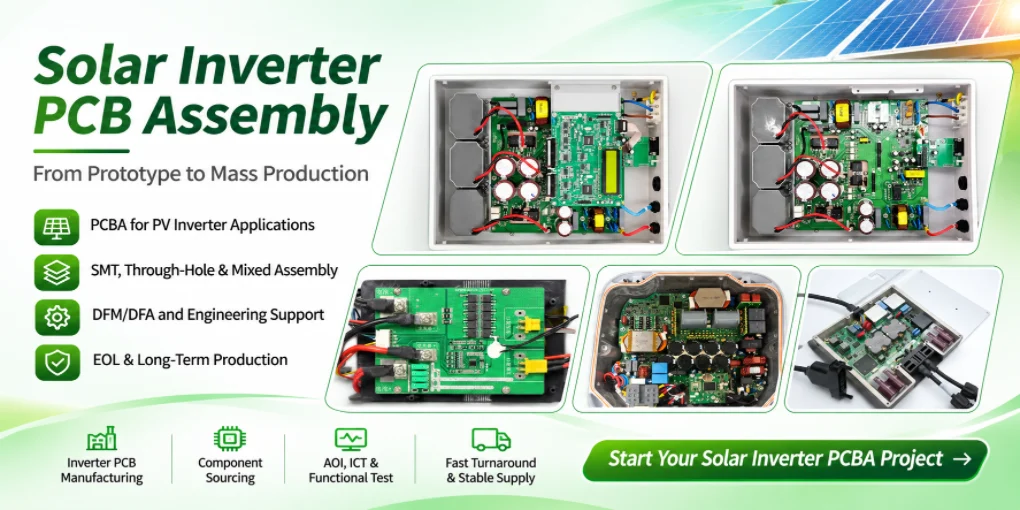
If you are sourcing Solar Inverter PCB Assembly, Highleap Electronics can evaluate the complete inverter PCB package—not only a single populated controller board. Our China-based PCB and PCBA services combine fabrication, electronic component purchasing, SMT and through-hole assembly, programming, inspection and customer-defined functional testing. For a solar inverter OEM, the manufacturing package may contain separate MPPT, DSP/control, gate-driver, sensing, auxiliary power, relay-control and communication PCBAs, each with different requirements and the same product release deadline.
We work from the customer’s approved schematic, stack-up, BOM, assembly documentation and acceptance instructions. Whether the product is a residential hybrid solar inverter, three-phase string inverter, microinverter, off-grid inverter or battery storage inverter, the goal is to deliver correctly matched boards that can be integrated into the OEM’s qualified equipment. Highleap does not treat end-product grid certification as an automatic by-product of PCB assembly.
Solar inverter PCBA sourcing snapshot
One RFQ can cover the power conversion controller + MPPT board + gate-driver interface + sensing/protection PCBA + communication board + battery interface, with separate pricing for manufacturing, purchased components, programming, test fixtures and optional finishing. Board-level scope and system-level testing must be distinguished in the quote.
Solar Inverter PCBAs and Companion Boards to Source Together
A solar inverter manufacturer typically purchases a coordinated set of power, control and interface assemblies. The exact arrangement varies by string, microinverter, central, hybrid or off-grid architecture, but most procurement problems appear where those boards meet: connector pinouts, isolation domains, firmware revisions, DC-link sensing and mechanical stack-up.
Residential, commercial and utility-side inverter products
String inverter PCB assembly: DC input/MPPT control, gate-drive interfaces, grid sensing, protection circuits, auxiliary power, cooling control and communication modules for single-phase or three-phase systems. Large commercial string inverters can require multiple synchronized controllers and independent monitoring boards.
Hybrid solar inverter PCB assembly: the above inverter control families plus bidirectional battery DC/DC controls, battery-management communication, transfer/relay-control circuits and power monitoring. The boundary between inverter and battery system must be documented to prevent wrong connectors or conflicting firmware options.
Microinverter PCB assembly and module-level electronics: compact boards with dense power conversion, sensing, communication and environmental packaging constraints. Thermally challenging layouts may require special substrate or interface reviews, but the suitability of any material must be evaluated from the customer’s design.
Off-grid and solar pump inverter PCBAs: controller, motor-drive or AC output interface, MPPT and auxiliary protection boards where required by the OEM. Solar water pump drive boards may combine inverter power control and motor-speed logic in one assembly.
Battery energy storage and monitoring: PCS controller boards, BMS communication interfaces, energy-management gateways, PV combiner monitoring and remote telemetry PCBAs. These are closely related solar power electronics sourcing opportunities, but their operating voltages and safety functions are not interchangeable.
Highleap’s existing renewable-energy power electronics manufacturing scope makes it possible to discuss the board family instead of pricing an MPPT board in isolation. Include the product board map and quantities per finished inverter so the material kits and production releases can be coordinated.
Fabrication and Assembly Details That Decide Solar Inverter Production Yield
Solar inverter control electronics often put low-level current sensing close to noisy switching environments, while separate PCBAs may carry appreciable current or host large electromechanical parts. The correct process must be selected by board function—not simply by the inverter’s advertised kilowatt rating.
| Board in the inverter | Fabrication / population focus | Acceptance decision |
|---|---|---|
| MPPT and control PCBA | Multilayer control PCB, ADC/reference components, MCU/DSP, isolated interfaces and programming access | Approved measurement and control test points |
| Gate-driver / sensing PCBA | Isolation geometry, creepage/clearance, driver packages, current sensors, connector pinout | Electrical isolation and controlled driver checks as specified |
| DC input or power interface board | Conductor copper and thermal rise, high-current terminals, protective components, heavy thermal mass | Dimensions, current-path integrity and specified safety checks |
| Grid / battery relay-control board | Mixed SMT/THT, relay or contactor drivers, power supply and sensing | Output switching and fault-state verification |
| Communication and HMI PCBA | RS-485/CAN/Ethernet/Wi-Fi interfaces, connectors, indicators and firmware | Correct configuration, protocol and serial identity |
Highleap supports multilayer and custom PCB fabrication and heavy-copper PCB construction where the stack-up warrants it. High-current capability still depends on conductor dimensions, thermal conditions and the OEM’s design verification. A heavy copper trace does not replace a correctly rated module, busbar or connector.
The assembly review should also identify through-hole magnetics and connectors, high-voltage capacitor polarity, heat-sink positioning and access for bottom-terminated device inspection. Before issuing production tooling, use DFM/DFA review for PCB assemblies to confirm stencil geometry, selective-solder reach, insulation slots, component spacing and programming/test pads.
Solar Inverter Power-Stage PCB Assembly and Control-Board Manufacturing
Solar inverter PCBA manufacturing usually involves several board functions that should be reviewed separately before they are released as one product set. The MPPT and DSP control boards handle measurement, control and communications; gate-driver boards interface with switching devices; power-interface boards carry defined current paths; and relay or battery-interface boards manage specified switching and system connections. The exact partition depends on the inverter architecture and the OEM’s design.
For power-stage and interface assemblies, the manufacturing package may include large DC-link capacitors, inductors, transformers, relays, contactors, high-current terminals, current sensors and power semiconductor interfaces. These parts can require a different process sequence from fine-pitch controller components. The DFM review should consider component mass, pad thermal relief, through-hole barrel fill, solder access, polarity, mechanical retention and the clearance needed for insulation components and mounting hardware.
Board-specific checks before the production release
- MPPT and DSP control boards: confirm MCU/DSP variants, clock and memory parts, analog reference components, programming access and calibration data.
- Gate-driver boards: verify driver and isolation components, connector pinout, fault feedback, polarity and the customer’s defined isolation test boundaries.
- DC input and power-interface boards: review copper construction, terminal ratings, capacitor polarity, current-sense components and thermal interfaces.
- Relay and battery-interface boards: confirm relay or contactor variants, coil-drive circuits, communication interfaces and mechanical clearances.
- Communication and HMI boards: verify the required RS-485, CAN, Ethernet or wireless components, firmware identity and connector configuration.
For a hybrid inverter, the RFQ should identify which boards communicate with the battery-management system and which functions remain within the inverter controller. For a microinverter, the mechanical envelope, thermal path and environmental finishing may be particularly important. For a three-phase string inverter, provide the board quantities per unit and identify any synchronized control or sensing assemblies. These details help the factory prepare matched material kits and avoid quoting one board without the related hardware needed for the build.
From prototype inverter PCBA to repeat production
Use the prototype or pilot build to confirm connector mating, board-to-board compatibility, firmware revision, calibration procedure, assembly access and the agreed functional test. Record deviations and approve any design or BOM changes before the production package is frozen. The factory’s board-level test report should state exactly which functions and limits were checked; grid connection, anti-islanding, full-power efficiency, EMC and product safety qualification remain separate system-level activities unless expressly included in the approved project scope.
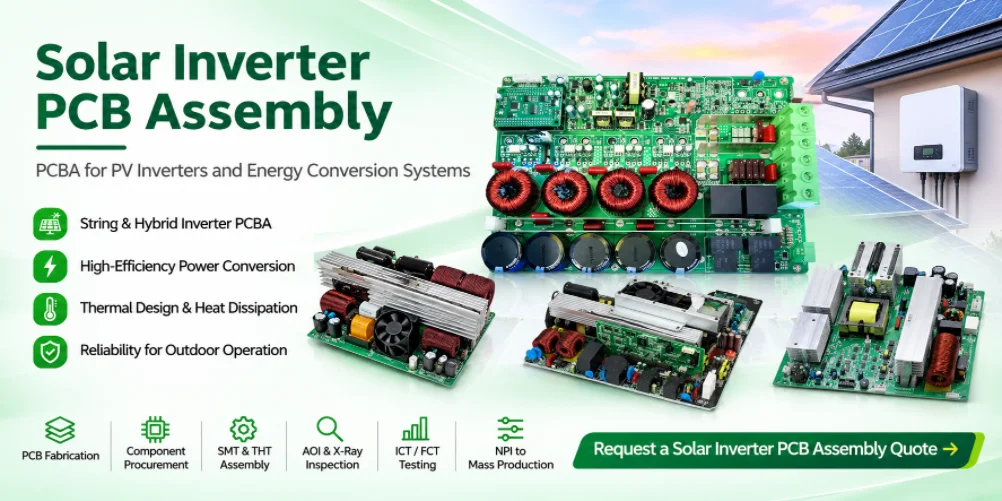
A Turnkey Supply Plan for String, Hybrid and Microinverter OEMs
Consolidating PCB manufacturing and assembly is valuable when it keeps all inverter boards on one controlled bill of materials and engineering revision. It is not enough for a factory to say “turnkey”: the RFQ must identify whether it includes electrical components, optional modules, cable sets, pre-programming, fixture costs and final packaging.
Power devices, microcontrollers, isolated transceivers, precision sensing ICs, connectors and DC-link-related components often have specific approved suppliers. Through electronic component sourcing, the purchaser can compare full turnkey against an OEM-consigned arrangement for critical chips. Highleap should receive the approved alternates list and any EOL/NRND restrictions before orders are committed. A pin-compatible substitute may alter insulation, efficiency, grid-control timing or firmware behavior.
We recommend a single NPI package with the following release identifiers:
- Every board’s part number, fabrication revision and approved stack-up;
- BOM revision, approved alternates and purchaser responsibility;
- Firmware image or bootloader version and any calibration/serial data;
- Board-to-board connector and cable revision;
- Test sequence, fixture identity and acceptance limits;
- Delivery group: boards shipped as separate PCBAs, matched kits or integrated units.
For recurring orders of the same inverter model, the approval system should record any change to the current-sense chain, gate-driver IC, isolation part or programmable device. Procurement savings on one BOM line can be outweighed by the cost of a hardware retest or field incompatibility.
Highleap’s SMT and through-hole PCBA manufacturing can be quoted with one-stop turnkey board production. Ask the factory to distinguish standard board assembly from additional power-module installation, cable work, heat-sink attachment and enclosure integration before approving the commercial scope.
What We Test Before an Inverter PCBA Leaves Manufacturing
A solar inverter board can pass solder inspection and still fail its intended control function. The acceptance plan should therefore be designed from the customer’s board-level functions and should not claim to replace complete inverter qualification.
Our standard service portfolio includes AOI, X-ray inspection and project-specific functional PCBA tests. For solar inverter control PCBAs, a suitable production test discussion might cover:
- Power supply startup, undervoltage response, current consumption and regulated rails;
- MPPT control board analog-input points and calibrated current/voltage measurement channels;
- Gate-driver enable/inhibit behavior, driver power, fault propagation and isolation-related checks using safe fixtures;
- Relay/contactor-driver outputs and approved interlock logic;
- Battery interface communications, RS-485/CAN/Ethernet connectivity, HMI and firmware identification;
- Traceability of firmware, measured values and board revision to serial or production lot.
High-power energization, grid interconnection, anti-islanding, EMC, surge, thermal endurance and certification testing remain part of the end-product validation program unless the contract specifically allocates those tasks to an approved service provider. For relevant markets, the OEM may specify IEC 62109 safety requirements and, for North American distributed-energy equipment, UL 1741 or applicable interconnection rules. A PCBA functional pass is not an IEC/UL product approval.
Outdoor solar equipment may require additional protection against condensation or contaminants. Highleap offers selective conformal coating as a possible finishing operation. Coverage maps must exclude mating contacts, thermal interfaces and test pads as specified, and coating suitability must be established for the actual environment; it does not waterproof an inverter by itself.
Solar Inverter PCB Assembly RFQ: Send the Entire Board Package
If you are looking for a solar inverter PCB assembly manufacturer in China, the most useful RFQ includes all boards required for one complete inverter model. That lets Highleap assess lead-time-critical parts and interdependent revisions instead of quoting each board without system context.
Attach the board list and quantities per inverter, Gerber/ODB++ or equivalent, fabrication drawings, stack-ups and copper specifications, BOMs with manufacturer part numbers, SMT placement files, assembly drawings, high-voltage/insulation notes, firmware requirements, intended board-level test procedures, prototype and annual forecast quantities, and any requested coating or electromechanical integration.
For hybrid inverter programs, identify whether the request includes battery DC/DC control, BMS communication, energy-management gateway and grid relay boards; for microinverters, call out mechanical envelope, thermal interfaces and any potting or environmental finishing; for commercial string inverters, provide the release schedule for all controller, sensing and communications PCBAs.
Three Details That Make a Solar Inverter PCBA Quote More Accurate
Specify the board-level voltage boundaries: a solar inverter’s stated DC input range is not automatically the voltage applied to every control PCB. Identify the maximum voltages at each board or connector and the required isolation interface. This determines which circuit-board dimensions, clearances and test fixtures need attention.
Separate firmware release from parameter calibration: a string inverter controller, hybrid battery interface and microinverter communication board may use separate firmware builds or region-specific settings. Define the images, programming method and any customer-controlled grid parameters as manufacturing inputs. The factory should not select regional operating parameters on its own.
Request a pilot-board set before placing a volume order: verify connector mating, control-board compatibility, firmware/PCB revision and the approved functional test sequence on an agreed sample lot. Then freeze the production package. This is especially valuable for three-phase solar inverter PCB assembly and hybrid solar inverter PCBA manufacturing, where one unapproved alternate can affect several related boards.
Highleap Electronics — Solar Inverter PCB & PCBA Manufacturing RFQ
Send your string inverter, hybrid inverter, microinverter or PV energy storage PCBA documentation. We can prepare a project-specific manufacturing discussion covering bare boards, components, assembly, programming, functional tests and optional protective finishing.
Scope clarification: the exact power-board manufacturing process, test equipment, coating and packaging arrangement, production yield expectations and compliance responsibilities are determined during RFQ and engineering release. End-product efficiency, grid-code and safety approvals remain subject to the OEM’s qualification plan.

Recommended Posts
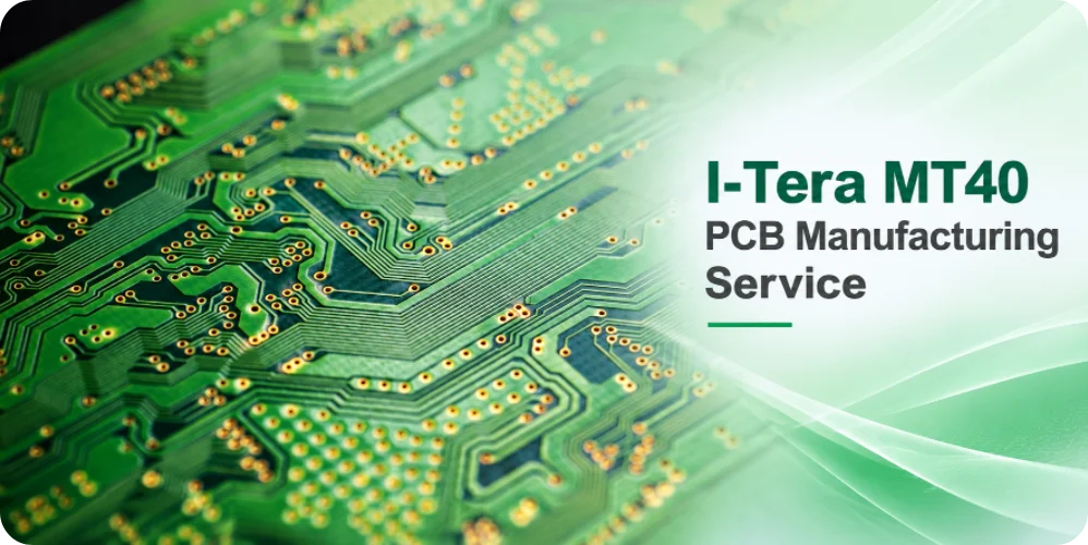
I-Tera MT40 PCB Fabrication Process and Verification
Highleap Electronics provides Isola I-Tera MT40 PCB...
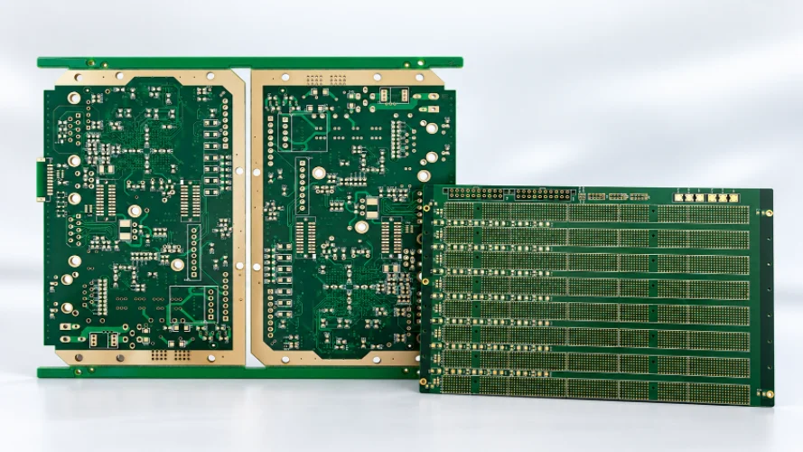
I-Tera MT40 PCB Supplier Qualification Checklist
Highleap Electronics manufactures printed circuit boards...
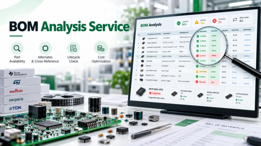
PCB Assembly with Free BOM Analysis Service
Need a free BOM analysis service before committing to PCB...
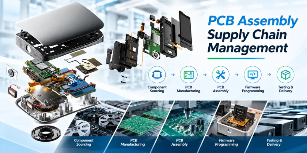
PCB Assembly Supply Chain Management
Highleap Electronics supports PCB assembly supply chain...
How to get a quote for PCBs
Let‘s run DFM/DFA analysis for you and get back to you with a report. You can upload your files securely through our website. We require the following information in order to give you a quote:
-
- Gerber, ODB++, or .pcb, spec.
- BOM list if you require assembly
- Quantity
- Turn time
In addition to PCB manufacturing, we offer a comprehensive range of electronic services, including PCB design, PCBA, and turnkey solutions. Whether you need help with prototyping, design verification, component sourcing, or mass production, we provide end-to-end support to ensure your project’s success.
For PCBA services, please provide your BOM (Bill of Materials) and any specific assembly instructions. We also offer DFM/DFA analysis to optimize your designs for manufacturability and assembly, ensuring a smooth production process.