
Portable Media Player PCB Manufacturing & PCBA for Audio and Battery-Powered Devices
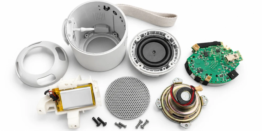

A compact MP3 player and a high-resolution digital audio player can use the same basic functions—storage, decoding and audio output—yet require very different PCB assemblies. One might use a single populated board behind a small display. The other may separate its processor, DAC, headphone amplifier and side-button circuits to fit a thin enclosure or meet its specified audio performance. For a PCB manufacturer, the important question is which assembled boards belong to the released player design, not how many features appear on its product label.
Highleap Electronics manufactures customer-designed portable media player PCBs and PCBAs, including audio, main control, display-interface and power-related boards. Our electronic manufacturing services can cover bare PCB fabrication, approved component procurement, SMT and through-hole assembly, and agreed programming or functional testing. The points below are intended to help OEM teams define a buildable board set, avoid costly material substitutions and prepare a meaningful production quotation.
Portable Media Player PCB Assemblies by Device Type
Not all media players have a separate audio board, and not all compact products put every function on a single mainboard. The enclosure, user interface and approved electronics determine how many PCBAs are required. Common manufacturing arrangements include:
- Basic MP3 players: An integrated decoder or MCU board may carry flash or microSD storage, headphone output, keys and charging circuitry. A small display or button FPC may be the only additional interconnect.
- Hi-res digital audio players (DAPs): A processor mainboard may connect to a dedicated DAC, analog output or headphone-amplifier section. Some designs use separate rigid boards; others isolate these areas on the same PCB. The exact construction follows the released signal and mechanical design.
- Portable video and MP4 players: A larger display, memory and video-processing device can add dense packages, display FPC connectors and a second button or interface PCB. The display module itself is not necessarily part of the PCBA supply scope.
- Special-purpose playback devices: Audio guides, educational players and wireless music terminals may add a speaker amplifier, rugged buttons, Bluetooth/Wi-Fi hardware or a charging-contact board as specified.
This distinction changes quotation accuracy. A BOM for the mainboard cannot price an entire three-board player unless the audio sub-board, flex assembly and their connectors are also released. Conversely, quoting separate PCBAs that the OEM has already integrated into one board adds unnecessary scope. For a multi-board unit, state the part number, revision and quantity of each PCBA used in one finished player.
Audio PCB Assembly: DACs, Headphone Amplifiers and Output Quality
The audio path is where a portable audio player PCB assembly needs more specific manufacturing controls than a generic digital controller. The design may use an integrated codec, a separate digital-to-analog converter, an analog filter, headphone amplification or a speaker driver. Those alternatives cannot be inferred from labels such as “MP3” or “hi-fi”; the schematic and approved BOM define the circuit.
Which components should not be substituted casually?
DACs, audio codecs, low-noise regulators, amplifier ICs, reference parts, oscillators and some filter components can affect gain, output noise, channel behavior or firmware initialization. A footprint-compatible replacement may still require engineering approval. The same concern applies to headphone sockets: a connector with the correct number of contacts can have a different switching arrangement, insertion height or mechanical anchor.
When a device has a dedicated amplifier board, the manufacturing concerns overlap with audio amplifier PCB assembly: controlled analog components, solder cleanliness where relevant, connector grounding and verification under a defined load. Manufacturing should reproduce the customer-approved grounding, copper, decoupling and placement rather than promising to correct a noisy design through SMT alone.
A playback check that merely confirms audible music may miss reversed stereo channels, an incorrect output gain, intermittent jack contacts or switching noise from the display and charger. If the OEM needs these faults screened, it should specify test files or tones, output connectors, reference loads, volume settings and limits. Noise and distortion figures should never be invented as a standard result of ordinary PCBA inspection.
Mainboards, Storage and Display Interconnections
A media player’s processor, flash or eMMC, microSD socket and display are connected by more than a placement drawing. Storage part changes can affect boot configuration, timing, voltage requirements and firmware compatibility. For removable media, a socket also has physical requirements: card orientation, retention, detect contacts where fitted and alignment with the enclosure opening.
A production-ready MP3 player PCB assembly should identify whether firmware is preloaded into supplied memory, programmed after reflow or installed during final device assembly. If several capacities or market versions share the same copper design, the BOM, firmware image and test media should distinguish them. These are build variants, even when the bare PCB part number is identical.
When does a separate control or display PCB make sense?
A narrow display, side-mounted buttons or a thin housing may require a flex tail or a separate control board. In such products, flex PCB assembly becomes relevant to component mounting, stiffener location, FPC insertion and the intended fold during installation. A static installation fold is different from a cable that bends repeatedly during use; the released flex construction must match its duty.
For the first assembled sample, check whether the display connector, buttons, volume control and headphone jack fit their actual mechanical positions. An electrically functional loose PCBA may still be unusable if a flex connector faces the wrong way or a side switch misses its enclosure actuator.
Battery Charging and Power Management for Portable Players
Most battery-powered players have several meaningful operating states: startup, library scanning, playback with the screen off, playback with the display active, charging and standby. The power supply is not exercised equally in all of them. A regulator or USB connector that passes a no-load inspection may behave differently when the amplifier, storage interface and display are active together.
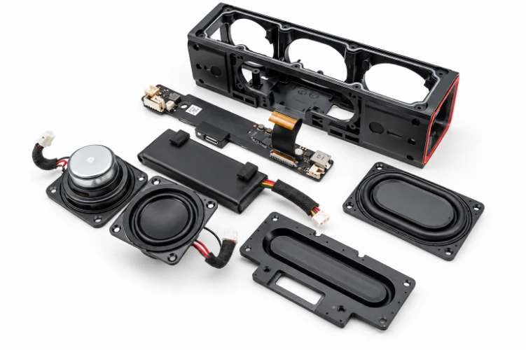
The charging IC, battery connector, thermistor input, protection parts and power-path components should follow the approved electrical design. A separate battery management board is possible but is not a default requirement for small players; charging and protection are often integrated into the main PCB or battery pack. The relevant manufacturing discussion is therefore battery charger PCB manufacturing and assembly of the specified power circuitry, not an assumption that every device has an independent BMS.
Before quoting test operations, identify the battery or approved power simulator, charging source and intended acceptance states. If the player has Bluetooth or Wi-Fi, antenna keep-outs and radio configuration must also follow the release. Finished-product battery endurance and wireless regulatory testing are separate from standard board-level acceptance unless explicitly included.
Have the Player Mainboard and Audio BOM Ready?
Send the board files and BOM with the codec or DAC part numbers, memory configuration, display/FPC details, charging circuit and required playback checks. If your player uses several PCBAs, identify the quantity of each board per unit. Highleap can review the defined fabrication, component and assembly scope before quotation.
| Get My Quote | Discuss My Build |
From SMT Assembly to a Repeatable Playback Test
A portable media player PCBA can contain fine-pitch QFNs, processor or memory packages with hidden joints, small analog passives, reinforced headphone connectors and flex sockets. A practical assembly plan addresses the actual package mix, component moisture requirements, board support, post-reflow connector operations and the inspection coverage appropriate to those parts. AOI or visual inspection finds many placement and solder defects, but it cannot demonstrate that audio plays correctly through the selected output.
A useful acceptance sequence for the released player
- Identify the build: Confirm the PCB/BOM revision, audio IC and memory configuration, and firmware version where programming is included.
- Boot and access storage: Start the board or agreed test assembly and read a known file from the specified internal storage or removable card.
- Verify playback: Check the intended headphone or speaker output, left/right channel mapping, mute and volume behavior under the approved test load.
- Exercise user interfaces: Verify fitted buttons, display, card-detect and USB or wireless functions against the product variant.
- Check power behavior: Confirm the customer-defined playback, charging and standby states and any necessary power-cycle recovery.
The factory does not need to perform every item above on every project; the test depends on what is assembled, accessible and included in the quotation. Highleap can discuss PCB assembly functional testing against agreed firmware, reference files, fixtures and limits. Detailed acoustic tuning, battery-life qualification and complete wireless certification remain product-level work unless separately contracted.
Before a repeat run, keep the accepted hardware revision, approved audio and memory parts, programming image, output-load fixture and test script together. Otherwise a new memory device or codec revision can cause a functional-test failure that looks like a soldering fault. Traceable changes are more useful than increasing inspection steps without a defined failure mode.
What to Send for a Portable Media Player PCBA Quote
The most useful quotation distinguishes bare PCBs, populated PCBAs and any additional module installation. A buyer requesting only audio and main control boards should not pay for assumed enclosure assembly; likewise, a quotation for one PCB should not silently omit a required button or charging sub-board.
- Fabrication: Gerber, ODB++ or IPC-2581 data, board outline, stack-up, thickness, surface finish and any impedance or flex notes.
- Assembly: BOM with approved manufacturer part numbers, component placement data, assembly drawings, do-not-populate details and any consigned components.
- Player electronics: Codec/DAC, amplifier and processor identities; storage and display specifications; connector/FPC drawings; battery and charging details.
- Programming and acceptance: Firmware/configuration files where required, playback reference files, headset or electronic loads, fixture instructions and pass/fail criteria.
- Commercial scope: Boards required per finished player, engineering-sample quantity, planned production batches, delivery destination and which materials the OEM will supply.
For a first build, component minimum purchases, setup time and fixture preparation can dominate the price. For repeat orders, the more useful comparison is the total assembled-board cost, material continuity and testing time under a fixed revision. A cheaper substitute that changes the audio path or firmware can create more cost than it saves.
If one supplier is to coordinate board fabrication, approved component purchasing and assembly, Highleap’s turnkey PCB assembly can be quoted for the released board set. Sending a complete player-specific package makes it possible to discuss a real production order rather than an undefined “MP3 player board” price.

Recommended Posts
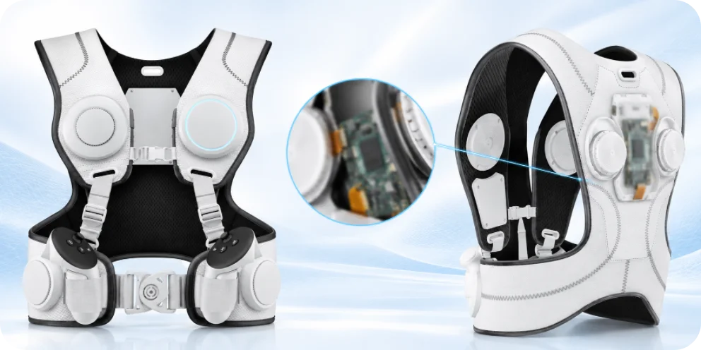
Wearable Haptic Vest PCB Manufacturing & Assembly for Multi-Zone Haptic OEMs
In a wearable haptic vest, the wearer notices the...
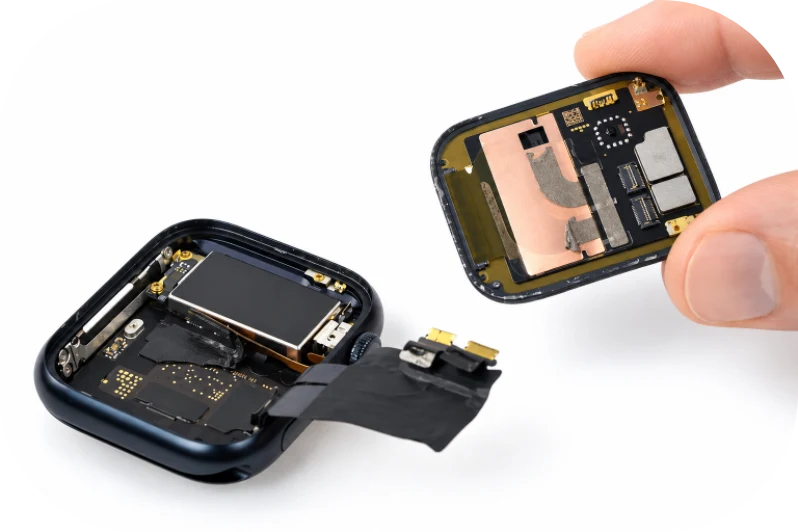
Wearable Temperature Logger PCB Manufacturing & Assembly for BLE Sensor OEMs
A wearable temperature logger PCB is the electronic board...
Connected Safety Helmet PCB Manufacturing & Assembly for Industrial IoT OEMs
A Connected Safety Helmet PCB is an industrial IoT...
Mobile Wi-Fi Router PCB Manufacturing & Assembly for 4G/5G Hotspot OEMs
A Mobile Wi-Fi Router PCB is the production platform...
How to get a quote for PCBs
Let’s run DFM/DFA analysis for you and get back to you with a report. You can upload your files securely through our website. We require the following information in order to give you a quote:
-
- Gerber, ODB++, or .pcb, spec.
- BOM list if you require assembly
- Quantity
- Turn time
For PCBA services, please provide your BOM (Bill of Materials) and any specific assembly instructions. We also offer DFM/DFA analysis to optimize your designs for manufacturability and assembly, ensuring a smooth production process.