
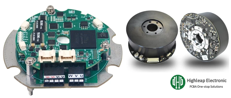
Robot Joint Driver PCBA Supplier Evaluation Checklist

Programs with tight schedules typically reduce handoff friction by aligning board construction with assembly scope early; that’s easiest when the supplier can coordinate PCB fabrication and PCBA manufacturing as one controlled package.
Table of Contents
- What to Freeze Before RFQ (So Quotes Are Real)
- Genuine Components: Channel Rules and Anti-Counterfeit Proof
- Quality Expectations That Matter for Robotics Drives
- Lead Time: What Drives Schedule and How to Prevent Slips
- What You Should Receive With Every Shipment
- Related Robotics Products to Build in the Same Program
What to Freeze Before RFQ (So Quotes Are Real)
Most “late delays” and “unexpected quality issues” come from missing constraints. A joint driver RFQ should communicate boundaries that affect price, lead time, and yield—without forcing you to manage factory details.
- Operating envelope: DC bus range, continuous/peak phase current, switching frequency range, ambient temperature, and duty cycle profile (continuous torque vs burst motion, braking frequency).
- Mechanical constraints: connector types, cable direction, retention needs, vibration exposure, and heatsink/TIM interface requirements if the PCBA mounts to a cold plate or enclosure.
- Critical parts list: identify “no-alternate” parts and “approved alternate” parts, especially for power semiconductors, shunts, isolators, and high-spec connectors. Define parameter equivalence rules (not only footprint/value).
- Board construction intent: copper weight, thickness, and any heavy-current regions; if the design relies on thick copper for current/thermal margin, align early with heavy copper PCB capability.
- Test intent: specify what must be verified at end-of-line (protection thresholds, current regulation under load, comms under switching, encoder validity) and what must be recorded.
Genuine Components: Channel Rules and Anti-Counterfeit Proof
Counterfeit and grey-market parts are a real risk in robotics drives because failures often appear only under thermal and switching stress. To protect reliability without slowing procurement, use channel rules and auditable evidence for defined critical BOM lines.
Parts That Should Default to “No Substitute”
- Power stage devices: MOSFET/IGBT, gate driver ICs, isolated drivers—alternates can change switching loss, timing, EMI, and fault behavior.
- Sensing chain: shunt resistors (TCR/long-term stability), op-amps/amplifiers (offset/drift), references—alternates can move torque accuracy and trip thresholds.
- Isolation components: isolated DC/DC, digital isolators—must meet working voltage and safety ratings.
- DC-link capacitors and snubbers: ESR/ESL and ripple ratings impact bus ripple and heating; uncontrolled alternates can cause resets and comms instability.
- Connectors: retention, mating cycles, vibration rating—substitutes often fail mechanically first.
Channel Control That Scales
- Authorized sourcing for critical lines: require procurement from franchised distributors or manufacturer-authorized channels for the critical list.
- Alternate approval workflow: allow alternates only from an approved list or with written engineering approval confirming key parameters.
- Proof on request: require invoice/trace documents and lot/date code capture for selected semiconductors and isolators.
If you want sourcing + assembly controlled under one accountable scope, structure it as turnkey PCBA so component authenticity and alternate rules are enforced consistently across builds.
Quality Expectations That Matter for Robotics Drives
For joint drivers, the costly problems are usually intermittent. Quality requirements should focus on failure modes that drive field returns: thermal instability, connector fatigue, sensing drift, and EMI-sensitive faults. A good supplier will turn these requirements into risk-based inspection and test coverage.
- Power device joints: require evaluation of hidden joints and thermal pads using defined X-ray criteria and a sampling plan that matches risk (higher for new revisions and early ramps).
- High-current interfaces: define acceptance for DC input and phase output joints plus mechanical reinforcement/strain relief when cables apply load.
- Cleanliness for precision sensing: if the design includes high-impedance sensing or references, require a residue/cleanliness plan to avoid drift and intermittent leakage behavior.
- Inspection coverage that is repeatable: request structured inspection outputs via inspection and quality control rather than ad-hoc photos.
Lead Time: What Drives Schedule and How to Prevent Slips
In robotics drives, lead time is mostly a supply-chain and readiness problem. The best schedules come from controlling the critical path early and preventing revision churn.
- Critical-path components: power devices, isolators, specialty capacitors, and connectors often set the schedule. Confirm availability and lock quantities per build stage (EVT/DVT/PVT/MP).
- Revision control and change cutoffs: define a change-freeze date per build. Late BOM swaps and footprint changes are the #1 cause of schedule resets.
- Programming and configuration readiness: if production requires flashing/config control, include it in scope using IC programming to prevent “wrong firmware” escapes.
- Test fixture readiness: define end-of-line coverage early so fixtures and limits are not invented during ramp. Where feasible, align to functional testing (FCT) requirements before the first pilot build.
What You Should Receive With Every Shipment
Shipment evidence should make incoming acceptance fast and containment efficient. Ask for a small set of high-value deliverables that actually reduce your risk.
- Certificate of Conformance (CoC): build revision, quantity, and compliance to the agreed acceptance criteria.
- Inspection summary: what coverage was applied (SPI/AOI/X-ray/visual), defect categories found, rework counts, and key observations tied to risk zones.
- Functional test report: pass rate and key measured values (protection thresholds, current regulation checks, comms checks), with firmware/config version if applicable.
- Component authenticity evidence: for critical BOM lines, provide trace documents upon request and record lot/date codes for selected semiconductors.
If your build includes an enclosure, harness, labels, or final assembly checks, define the delivery as a module and validate interfaces through box build assembly so quality is proven at the integration level.
Related Robotics Products to Build in the Same Program
Robotics teams often bundle multiple assemblies under the same quality and sourcing rules to reduce integration risk and supplier overhead.
- Power distribution and protection: DC bus boards, pre-charge circuits, e-fuse modules, voltage/current monitoring boards.
- Brake and safety electronics: brake driver boards, safety I/O expanders, fault aggregation modules.
- Sensor interface modules: encoder/resolver interface boards, IMU/force sensor hubs, isolated analog input modules.
- Communication gateways: CAN-to-Ethernet, EtherCAT nodes, isolated RS-485 hubs, diagnostic adapters.
- Auxiliary actuator electronics: gripper motor drivers, small-axis drives, fan/pump controllers, and power management boards.
Summary: A dependable robot joint driver PCBA program is achieved by locking critical requirements before RFQ, enforcing genuine sourcing with controlled alternates, planning lead time around true bottlenecks, and receiving shipment evidence that enables fast acceptance and rapid containment.

Recommended Posts

LED High Bay Light PCBs: Metal-Core Light Engines, Drivers & Turnkey Boards Built to Spec
Figure 1. LED high bay light PCB manufacturing reference....
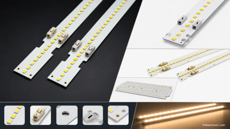
LED Linear & Strip Light PCBs: Long-Format Engines, Flexible & Rigid-Flex Boards
Figure 1. LED linear light PCB manufacturing reference....

LED Grow Light PCBs: Multi-Channel Spectrum Boards, Drivers & Thermal Design
Figure 1. LED grow light PCB manufacturing reference....
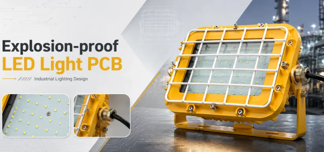
Explosion-Proof LED Light PCBs: Hazardous-Location Boards, Drivers & Assembly
Figure 1. explosion-proof LED light PCB manufacturing...
How to get a quote for PCBs
Let us run DFM/DFA analysis for you and get back to you with a report.
You can upload your files securely through our website.
We require the following information in order to give you a quote:
-
- Gerber, ODB++, or .pcb, spec.
- BOM list if you require assembly
- Quantity
- Turn time
In addition to PCB manufacturing, we offer a comprehensive range of electronic services, including PCB design, PCBA (Printed Circuit Board Assembly), and turnkey solutions. Whether you need help with prototyping, design verification, component sourcing, or mass production, we provide end-to-end support to ensure your project’s success. For PCBA services, please provide your BOM (Bill of Materials) and any specific assembly instructions. We also offer DFM/DFA analysis to optimize your designs for manufacturability and assembly, ensuring a smooth production process.