
Functional Safety PCB Design for Robot Controllers

Functional safety PCB design for collaborative robot controllers must prove one thing: when faults happen, the cobot safety controller PCB detects them and drives the system to a defined safe state within the required response time. Certification to IEC 61508 (SIL) and ISO 13849 (PL) depends on redundancy, diagnostic coverage, independence against common-cause failures, isolation integrity, and audit-ready evidence. PCB architecture and production consistency directly affect whether a cobot passes certification and stays compliant in volume production.
Highleap Electronics supports safety-related electronics builds by aligning controlled construction, assembly, and verification outputs needed for certification reviews. The focus is measurable: channel independence, isolation distances, diagnostic credibility, and documentation quality that stands up to audits—not just a board that powers on. For adjacent servo electronics that often share similar reliability and validation expectations in robotics programs, see our robot joint driver PCB assembly for servo motion overview.
Table of Contents
Functional Safety Standards for Cobot Controllers
Functional safety standards assess whether the implemented safety function meets risk targets and whether the development process is systematic and verifiable. For cobot safety controllers, reviewers will scrutinize how PCB-level decisions preserve independence, prevent dangerous fault propagation, and enable diagnostic coverage claims used in the safety case.
- Safety Integrity Levels (SIL): IEC 61508 defines SIL 1–4 based on probability of dangerous failure. Cobot safety functions commonly target SIL 2 and sometimes SIL 3, achieved through hardware fault tolerance, diagnostics, and systematic controls that match FMEDA assumptions.
- Performance Levels (PL): ISO 13849 defines PL a–e. Many cobot applications target PL d, typically using Category 3 architecture (redundant channels with monitoring) with high diagnostic coverage and controlled common-cause risk.
- Safe state definition: Certification starts from a defined safe state. For cobots this is often controlled stop followed by torque removal or power interruption, with feedback confirming the actual state matches the commanded state.
- Evidence expectations: Auditors approve documents and test evidence. Design rationale, FMEA/FM(E)DA outputs, verification reports, and production controls should be created during design so there are no gaps when certification begins.
Redundant Safety Architecture on the PCB
Redundancy provides fault tolerance only when channels remain independent and resistant to common-cause failures. The PCB is where independence is most often compromised—shared power conditioning, shared timing, shared routing choke points, or unintended coupling through ground and layout proximity.
- Physical channel separation: Implement clear placement and routing zones for each channel with controlled crossing points. Where keepouts are required, ensure they are manufacturable and enforced during CAM/DFM; coordinated PCB fabrication support helps prevent late-stage violations.
- Independent power domains: Each channel should have separate regulation and protection so a single component failure cannot collapse both channels. Split domains early and supervise each rail.
- Clock and reset independence: Avoid shared oscillators or reset generation as single points of failure. If any common reference is used, justify it in analysis and add detection/mitigation paths.
- Ground strategy as a safety decision: Whether using separated grounds or a controlled single reference, document the approach and analyze how it prevents fault coupling while meeting EMC requirements.
- Signal exchange without propagation: Cross-monitoring should not allow a short or stuck fault from one channel to force unsafe behavior in the other. Use buffering/isolation and defined pull states to bound failure behavior.
Diagnostic Coverage and Fault Detection Design
Diagnostic coverage is not automatic; it is designed. Safety controllers must detect dangerous failures with predictable behavior under noise, temperature, and aging. A strong design maps each credible dangerous fault to a detection method and a safe reaction, then proves it through verification testing.
- Output state monitoring: Safety outputs (contactor, STO, brake, relay) should include independent feedback confirming actual state. Auxiliary contacts, current/voltage sensing, or redundant confirmation paths reduce the risk of welded contacts or stuck outputs going undetected.
- Input plausibility checking: Redundant sensors/inputs should be checked for agreement, out-of-range conditions, and stuck faults. Define tolerance and timing windows to avoid both missed detection and nuisance trips.
- Hardware watchdog circuits: Independent watchdogs detect processor lockups and enforce safe state without relying on software. Timing design should be justified so it is neither too sensitive nor too slow for the safety reaction requirements.
- Self-test support: CPU, memory, and peripheral tests require stable power and clocking during execution; PCB design must support predictable references so self-test results are valid.
- Communication monitoring: Safety communication relies on CRC, counters, and timeout detection. PCB implementation should support stable timing and signal integrity to prevent false fault trips caused by layout-induced jitter or noise coupling.

Isolation, Creepage, and Clearance for Robot Safety PCBs
Isolation barriers prevent fault propagation between domains and are frequent audit focal points because spacing and leakage risks are measurable. PCB layout must maintain creepage and clearance not only “on paper” but also after assembly, rework, and environmental exposure.
- Isolation voltage specification: Select isolation components using working voltage plus credible fault conditions and surge margins, not only nominal operating conditions.
- Creepage and clearance rules: Define spacing requirements for surfaces and internal layers. A well-controlled multilayer PCB construction helps maintain distances across layers, cutouts, and planes.
- Digital isolator behavior under fault: Understand failure modes (open, short, undefined output) and design receiving circuitry so faults are detected or forced to safe outputs.
- Assembly impact on isolation: Residues, solder splash, and coating can reduce effective creepage or create leakage paths. Define assembly controls and acceptance to preserve isolation integrity.
Production Controls for Safety-Rated PCBA
Certification requires evidence that production assemblies match the analyzed design assumptions. The most effective approach is to define safety-critical characteristics and control them with targeted inspection, test evidence, and change control discipline.
- Material traceability (when required): For safety-critical components (supervision ICs, isolators, references, safety I/O), define sourcing rules and record critical lot/date information so investigations can separate systematic issues from random failures.
- Process validation: Validate manufacturing processes for the characteristics that affect safety claims—channel independence, isolation integrity, and diagnostic circuitry—not just generic cosmetic quality.
- Inspection and test records: Maintain inspection and test evidence in audit-friendly formats. Controlled PCB assembly documentation packages help demonstrate production consistency.
- Change control: Any change to parts, suppliers, materials, or processes should trigger a safety impact assessment and defined re-verification steps before release.
Certification Documentation and Audit Evidence
Certification bodies evaluate compliance through documentation. A strong documentation set provides traceability from safety requirements to design decisions, failure analysis, verification results, and production controls—so auditors can follow the logic without assumptions.
- Design rationale: Explain why the PCB architecture, isolation strategy, and diagnostics achieve the safety requirements. Where possible, map key decisions to standard expectations and to your safe state definition.
- FMEA / FM(E)DA coverage: Include PCB-related failure modes (opens/shorts, solder joint failure, contamination leakage, isolation breakdown) and document detection and mitigation for each.
- Verification test reports: Provide evidence for fault reaction time, diagnostic behavior, and safe state enforcement. Environmental and stress evidence can be supported through reliability testing when needed for operating condition robustness.
- Manufacturing documentation: Work instructions, inspection criteria, and process specs should be sufficient for auditors to confirm that production units implement the validated design.
For cobot programs, safety certification and production readiness are tightly linked: the PCB must be designed for fault detection and safe reaction, and production must be able to prove it with consistent evidence over the full product life.

Recommended Posts

Wireless Mechanical Keyboard PCB Manufacturing
Table of contentsWireless Keyboard PCB Procurement...

Split Keyboard PCB Manufacturing & Assembly
Table of contentsSplit Keyboard PCBA Procurement...
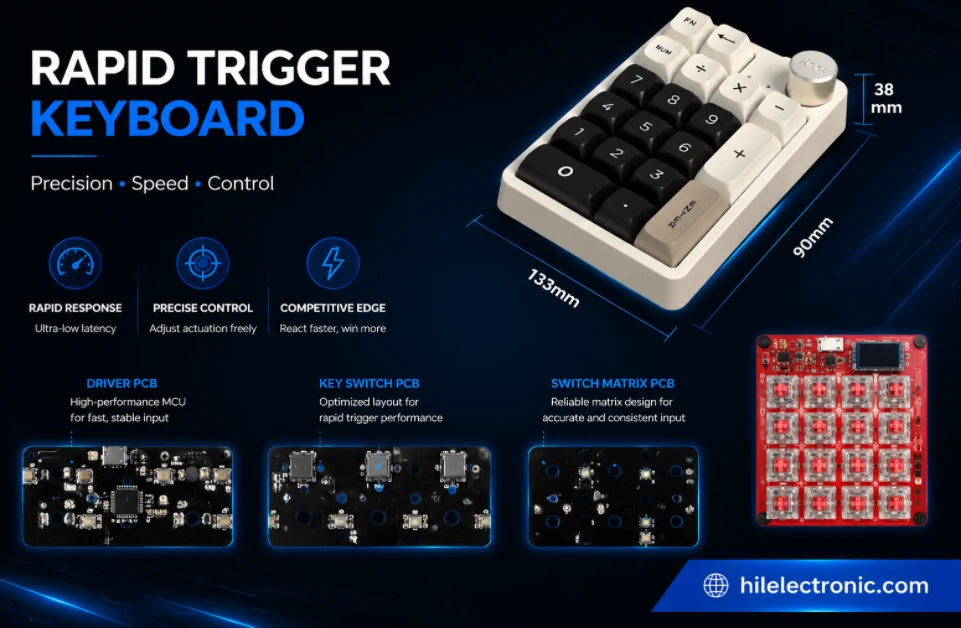
Rapid Trigger Keyboard PCB Manufacturing & PCBA
Table of contentsRapid Trigger PCBA Buying and Performance...
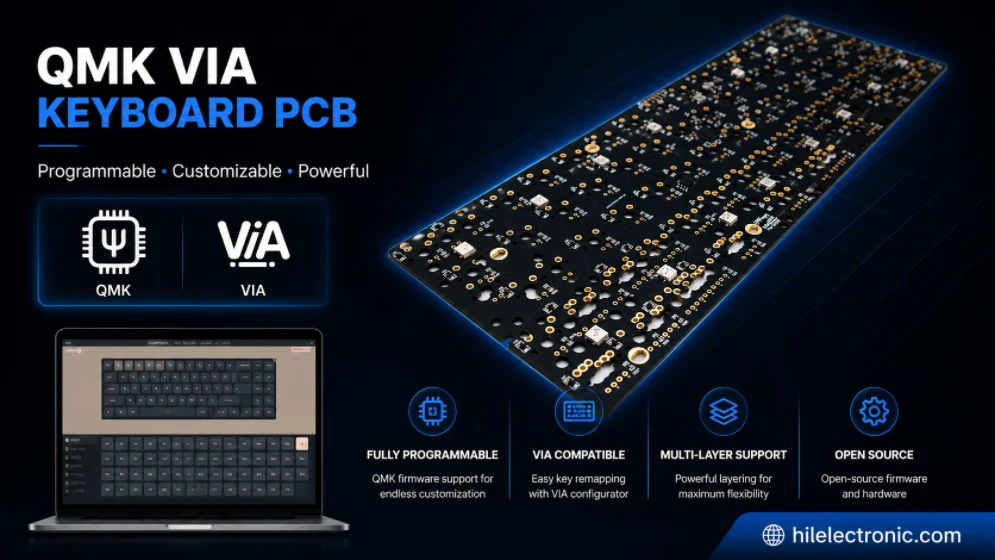
QMK/VIA Keyboard PCB Manufacturing & Assembly
Table of contentsQMK/VIA Keyboard PCB Buying...
How to get a quote for PCBs
Let us run DFM/DFA analysis for you and get back to you with a report.
You can upload your files securely through our website.
We require the following information in order to give you a quote:
-
- Gerber, ODB++, or .pcb, spec.
- BOM list if you require assembly
- Quantity
- Turn time
In addition to PCB manufacturing, we offer a comprehensive range of electronic services, including PCB design, PCBA (Printed Circuit Board Assembly), and turnkey solutions. Whether you need help with prototyping, design verification, component sourcing, or mass production, we provide end-to-end support to ensure your project’s success. For PCBA services, please provide your BOM (Bill of Materials) and any specific assembly instructions. We also offer DFM/DFA analysis to optimize your designs for manufacturability and assembly, ensuring a smooth production process.