
E-Reader PCB Manufacturing for Low-Power ePaper Devices
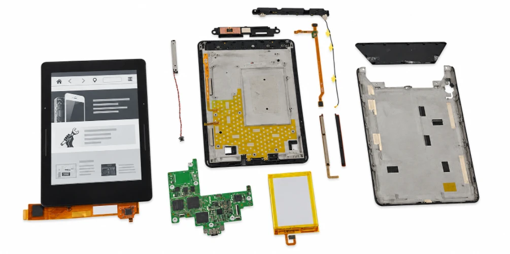
Table of contents
- E-Reader PCB Architecture: Low-Power Mainboard Rather Than Small Tablet
- ePaper Display Interface and Display-Drive Power Requirements
- Ultra-Low-Power PCB Design and Battery-Life Preservation
- Touch Sensing, Front-Light Control and User Interfaces Where Applicable
- Board Construction, Compact Placement and Flex Connections
- Fine-Pitch SMT Assembly and Low-Power Component Control
- Functional Validation for Display Update, Charging and Connectivity
- Sourcing and Supplier Selection for E-Reader PCB Production
An E-Reader PCB should not be treated as a smaller tablet motherboard. The defining system requirement is usually a low-power reading platform built around an electrophoretic or other ePaper display, with power consumed very differently from a continuously refreshed LCD/OLED product.
E Ink describes its ePaper technology as bistable: the image can remain visible without continuous display power, while energy is required when the image is updated. That characteristic shifts PCB priorities toward efficient standby behavior, controlled display-drive power, battery management and low-leakage system design.
Highleap Electronics supports customer-designed e-reader boards with PCB fabrication, fine-pitch assembly, sourcing and customer-defined functional testing. Touch, front light, Bluetooth, audio and cellular connectivity should be treated as optional functions unless the released product architecture includes them.
1. E-Reader PCB Architecture: Low-Power Mainboard Rather Than Small Tablet
An e-reader mainboard may include a low-power application processor or MCU/SoC, memory, storage, ePaper display interface, charging and battery-management circuits, Wi-Fi and product-specific controls. Touch sensing and front-light control are common in many current products but are not universal.
An e-reader should not be engineered as a lower-cost tablet. The defining system behavior is long standby/read time around a bistable electrophoretic display, so the mainboard architecture is often optimized for low quiescent current, efficient sleep states and infrequent display refresh activity. Processor choice, wireless duty cycle, touch subsystem, front light and storage all affect the power budget, but they do not imply a fixed PCB topology across every product.
Functional block and production relevance
| Block | Typical PCB role | Manufacturing focus |
|---|---|---|
| Processor / memory / storage | Runs the reader platform and stores content | Fine-pitch placement, power integrity, revision control. |
| ePaper display interface | Transfers image data and controls display-drive functions | Connector accuracy, clean routing, correct power-domain implementation. |
| Touch / front light (optional) | Adds user input and illumination | Flex connections, LED current paths, low-noise sensing. |
| Battery / charging | Supports portable operation | Polarity, current path, power-state validation. |
| Wi-Fi / Bluetooth (as designed) | Provides connectivity | Approved RF components, keep-outs and functional checks. |
For manufacturing, the important point is to preserve low-power intent while keeping the board mechanically compact. Leakage-sensitive nodes, wake signals, battery sensing and display-power circuits need clean assembly and controlled contamination; optional features such as audio or cellular should be treated as SKU-specific rather than generic e-reader functions. The RFQ should identify which features are fitted so sourcing and functional test are aligned with the exact device variant.
An e-reader is defined less by raw compute density than by how aggressively it manages energy between user interactions. The PCB may contain a capable application processor, but the product spends much of its time in low-power states while the electrophoretic display holds an image. That shifts manufacturing attention toward power-domain correctness, leakage-sensitive components, display-interface integrity and reliable wake/charge behavior rather than continuous high-performance cooling.
The display, touch sensor and front-light are often separate mechanical layers even when they connect to one mainboard. For production, each interface should be identified by exact module and connector data because a visually similar display can require different driver support, flex pinout or waveform configuration. SKU control also matters: some products omit touch, front lighting, audio or wireless features, so the PCBA population and functional-test plan must follow the released model rather than a generic “e-reader” feature list.
- Define the exact ePaper module and mating flex before PCB release.
- Separate always-on rails from switched domains in the test plan.
- Control optional touch/front-light/audio populations by SKU.
- Treat low-power current limits as measured acceptance criteria when they are production requirements.
2. ePaper Display Interface and Display-Drive Power Requirements
ePaper is electrically different from an LCD backlight system. The display module and its driver electronics can require dedicated waveforms and power rails for image updates. The exact driver IC, voltage generation and connector topology are display-platform decisions and should be taken from the approved design.
E Ink’s bistable behavior means the image can remain without continuous display power, but changing the image still requires a controlled drive sequence. In practical e-reader designs, the display subsystem may include a controller and power-management circuitry that produces panel-specific drive rails and waveforms. Exact voltages, temperature compensation and waveform tables depend on the display module and controller; they should never be generalized from one e-reader to another.
E Ink also notes that its display modules can be supplied with options such as touch panels or front lights. Consequently, the PCB should not assume those functions are part of the display itself; the project package must define which module stack is being used and which circuits are implemented on the mainboard.
Accuracy rule
Do not publish one “standard E-Reader PCB voltage” or a universal display-driver topology. ePaper families, sizes and controller solutions vary, so the manufacturer should build to the released display and power specification.
PCB manufacturing must protect the interfaces around this subsystem. Fine-pitch display connectors, flex tails and high-voltage-but-low-current display-bias nodes can require spacing, cleanliness and mechanical handling rules that differ from ordinary low-voltage digital nets. During NPI, verify that the assembled board can initialize the panel and complete defined refresh patterns without implying that the PCBA factory is qualifying the optical performance of the ePaper module itself.
Electrophoretic displays need drive electronics and update waveforms that are fundamentally different from continuously refreshed LCD/OLED panels. The PCB may include a display controller or interface device and power circuitry that generates the rails required by the chosen display platform. Those voltage levels, sequencing details and waveform data are design-specific; manufacturing should never infer them from panel size or substitute a display-related IC without engineering approval.
Connector quality is equally important. A display flex with high pin count and fine pitch can be vulnerable to incomplete insertion, damaged contacts or assembly stress. First-article validation should confirm connector orientation, latch operation, flex clearance and the ability to perform repeated image updates without visual artifacts attributable to the interconnect. If the display module requires configuration or calibration data, that information should be revision-controlled with firmware so repeat builds do not pair the same PCB revision with incompatible display settings.
Display handoff checkpoint
Provide the exact display-module part number, mating drawing and customer-approved functional pattern set with the RFQ. That lets the factory plan connector inspection and display-update testing around the real module instead of a generic ePaper assumption.
3. Ultra-Low-Power PCB Design and Battery-Life Preservation
Because the display can hold a static image without continuous refresh power, system standby consumption becomes especially important. Leakage through regulators, pull networks, peripherals or always-on rails can undermine the product’s low-power goal even if the display itself is efficient.
Long battery life is usually achieved by system-level power management rather than by one special PCB material. The board can support that objective through low-leakage component choices, short battery-sense paths, clean ground/reference strategy and careful separation of switching regulators from sensitive wake or sensing nodes. Firmware-controlled sleep states and radio scheduling often have as much influence as the PCB, so production hardware and firmware versions need to remain linked.
- Keep always-on and switched power domains aligned with the schematic and firmware power policy.
- Avoid unapproved substitutions in regulators, load switches, clocks or other parts that can change quiescent current.
- Control flux residue and contamination where high-impedance or low-leakage nodes are present.
- Use customer-defined current-consumption limits during functional validation when available.
The PCB factory can preserve the designed power paths and assembly cleanliness, but final battery life remains a system result affected by firmware, wireless activity, front-light use, battery capacity and user behavior.
Manufacturing cleanliness deserves more attention in low-current products than generic content often gives it. Flux residue, contamination, damaged high-impedance nodes or incorrect pull components can increase standby current without causing an obvious functional failure. A production plan can therefore include current-consumption checks at defined operating states when the customer provides limits and fixtures. That converts ‘low power’ from a marketing phrase into a measurable acceptance criterion.
Low-power production control starts with eliminating accidental current paths. Wrong resistor populations, flux contamination, damaged protection devices, incorrect pull networks or substituted regulators can all increase standby current without causing an obvious functional failure. For designs with tight sleep-current targets, a current-consumption check can therefore detect defects that ordinary power-on testing misses. The measurement method must specify battery or supply voltage, firmware state, settling time and instrument range to make results comparable.
Power sequencing and wake behavior should also be tested in realistic transitions. A board that boots correctly from a bench supply may still fail after deep sleep, charger insertion or an extended battery-disconnected state. During NPI, characterize the states that matter to the product—cold start, sleep, wake, display refresh and charging—and decide which are practical for production screening. This approach protects battery-life intent without forcing a full endurance test on every unit.
Highleap Electronics • PCB Manufacturing & PCBA
E-Reader PCB Manufacturing Review
Share the ePaper, power, battery and assembly package for a production-focused review.
Request an E-Reader PCB Quote →Discuss E-Reader PCBA →
✓ DFM and DFA review ✓ Prototype to repeat production ✓ PCB fabrication and assembly
4. Touch Sensing, Front-Light Control and User Interfaces Where Applicable
Touch-enabled readers introduce sensing lines and flex connections that may be susceptible to noise from digital and switching-power circuits. Front-light systems add LED drive current and mechanical dependence on the light-guide assembly. These functions should be separated in the layout and grounding strategy according to the customer design.
Touch and front-light functions are optional but common enough to require explicit architecture control. Touch may use a separate sensor/controller and flex connection, while the front light typically uses LEDs and a light-guide system driven from the main electronics. Neither should be described as part of the ePaper panel by default. Their PCB requirements include connector reliability, current control, EMI interaction and mechanical alignment with the display stack.
Buttons, LEDs, speakers or audio functions are similarly product-specific. A manufacturing article should describe them as optional interfaces, not standard blocks present in every e-reader.
The front-light driver is also a potential noise source in a device whose core display is otherwise low-power. Layout should keep switching loops controlled and prevent coupling into touch, audio or radio circuits. At the factory level, brightness stepping, touch response and button inputs can be checked against customer test criteria, while uniformity of the light guide and touch optical stack remains a final-product integration responsibility.
Low-power production checkpoint
For an e-reader NPI, define the display module, power states, current-consumption limits and optional touch/front-light/wireless features before quotation. This gives the factory measurable low-power and interface targets rather than a generic requirement for “long battery life.”
Touch and front-light circuits introduce two very different signal environments. Touch sensing can be susceptible to switching noise and ground disturbances, while LED front-light drivers can create fast current transitions that inject noise into nearby sensitive circuits. The design team sets filtering and layout strategy; manufacturing must preserve component values, grounding features, shield structures and flex routing. Late substitutions in touch-controller filters or LED-driver components should be reviewed for both electrical behavior and firmware compatibility.
Mechanical alignment matters because front-light performance depends on the complete optical stack, not just the PCB. Production testing can verify LED channels, brightness commands and current behavior, but uniformity across the reading surface is a system-level optical requirement. Likewise, a factory can verify touch communication and basic coordinate response, while final touch accuracy depends on sensor, cover material and calibration. Defining those boundaries prevents the PCBA test from being asked to certify characteristics it cannot physically measure.
5. Board Construction, Compact Placement and Flex Connections
E-reader electronics are generally space-conscious, but the board technology can range from conventional multilayer FR-4 to denser constructions depending on enclosure size and package choice. There is no valid universal layer count for the category.
E-reader boards are often compact, but compact does not automatically mean advanced HDI. Layer count, microvias and rigid-flex use should be justified by actual component pitch, routing density and mechanical folding needs. Where display or battery flexes connect to the mainboard, connector location and insertion direction must be checked against the enclosure because a small positional error can make final assembly impossible even when the PCB is electrically correct.
Small FPC connectors and perimeter interfaces often dominate mechanical risk. If flex circuitry is part of the product, flex PCB manufacturing requirements such as stiffener location, bend area and connector alignment should be controlled together with the mainboard drawing.
High-density via structures should be used only when required by escape and routing constraints. Overspecifying HDI can add unnecessary process complexity without improving the electrical design.
For thin boards, panelization and support during reflow can be important to flatness. Copper balance, tooling rails and carrier fixtures may be reviewed if the released board is susceptible to bow or twist. These manufacturing choices should be documented in the NPI record so repeat orders use the same process route rather than rediscovering handling solutions each time.
E-reader boards benefit from compact packaging, but the most reliable fabrication route is the least complex structure that meets the released geometry. Conventional multilayer FR-4 may be adequate for many designs; denser packages or smaller enclosures can justify HDI. The stack-up decision should be based on escape routing, controlled impedance where needed, finished thickness and component density—not on a blanket assumption that all modern e-readers require microvias.
Flex connections are often a bigger manufacturing risk than the layer count. Display, touch, buttons or front-light assemblies may connect through narrow flex tails near the enclosure edge. The PCB drawing should control connector position and board outline tightly enough for those tails to mate without twisting. If separate flex circuits are supplied, stiffener, coverlay and bend-zone requirements should be defined and inspected as part of the interconnect, not treated as an accessory after the mainboard is complete.
6. Fine-Pitch SMT Assembly and Low-Power Component Control
E-reader PCBA assembly may combine a processor, memory, storage, display/power ICs, wireless devices and small connectors on a compact board. First-piece verification should confirm polarity, option population and the display-interface connector before the batch proceeds.
An e-reader PCBA may combine fine-pitch processors or memory with relatively low-current peripheral circuits, which creates a broad component mix but not necessarily a high thermal load. Stencil design and reflow should still be optimized around bottom-terminated packages, FPC connectors and any shielded radio devices. The assembler should also control moisture-sensitive components and prevent unnecessary rework near fine-pitch display connectors.
The manufacturing scope can provide SMT assembly and targeted inspection. Hidden-joint packages can be reviewed by X-ray when specified, while visible components are suited to AOI. Low-power performance still requires electrical testing; visual inspection cannot reveal excessive standby current or incorrect power sequencing.
Low-power component control is especially important during sourcing. Regulators, load switches, pull resistors, oscillators and memory devices can influence sleep current or wake behavior even when replacements are nominally compatible. The approved BOM should therefore distinguish true alternates from parts that require engineering validation. This is a procurement issue as much as an electrical one, because unauthorized substitutions can quietly reduce battery life without creating an immediate factory failure.
Assembly process control should reflect the mixture of low-power ICs, fine-pitch connectors and small passives. Moisture sensitivity, paste volume and reflow exposure can matter for processors, memory and bottom-terminated power devices. First-piece review should confirm every optional population because an extra pull-up, LED channel or audio component may change standby current even if it does not prevent boot.
Cleanliness can be more important on low-current circuits than on robust digital products. Ionic residues or contamination around high-impedance nodes may create leakage or intermittent behavior that appears only under humidity. The appropriate cleanliness requirement depends on the design and reliability target, but it should be considered during process planning instead of assumed after failures appear. AOI, targeted X-ray and functional checks then cover different defect classes; none should be presented as a complete substitute for the others.
7. Functional Validation for Display Update, Charging and Connectivity
A useful e-reader test plan verifies the product-specific functions rather than a generic electronics checklist. Depending on the design and available fixtures, this can include programming, power-on behavior, display update, touch response, front-light control, charging, USB communication, wireless connectivity and current-consumption checks.
Functional test should reproduce the operations that matter to the production release: programming, power-on, display initialization, page refresh, charging detection, USB communication and wireless connectivity where fitted. Touch, buttons and front light can be added for variants that include them. The test should also check agreed current states if low-power performance is a critical acceptance item and the fixture can measure them repeatably.
Display testing should include actual update behavior because a connector or power-domain fault may not be visible on a static screen. Production can execute customer-defined functional testing when the required firmware, test assets and pass/fail limits are supplied.
Display testing needs a clear boundary. The PCBA factory can verify that the electronics command the module and that expected patterns appear, but ghosting, optical uniformity, front-light uniformity and final reading experience are influenced by the display module and mechanical stack. Separating electrical functional test from final optical qualification makes the manufacturing claim more credible and helps procurement compare quotations with equivalent scope.
A useful functional fixture should verify the sequence of functions that distinguishes an e-reader PCBA: controlled power-up, display communication, image update, sleep/wake, charging and any fitted touch/front-light/wireless functions. A simple “screen turns on” check is weak because an intermittent display flex or marginal power rail may pass once and fail during repeated update cycles. NPI can determine how many update patterns or state transitions are needed to catch assembly faults without making line test unnecessarily long.
Current measurement deserves its own test definition. Active refresh current, idle current and deep-sleep current are different states and should not be mixed into one limit. If the customer requires a production current check, the firmware build, measurement delay and connected peripherals should be fixed. This creates a repeatable gate that protects low-power performance while avoiding false failures caused by uncontrolled software or display activity.
8. Sourcing and Supplier Selection for E-Reader PCB Production
For an E-Reader PCB RFQ, identify the display module, touch/front-light options, battery interface, wireless configuration, approved parts and test criteria. This prevents the assembler from treating two visually similar e-reader SKUs as the same electronics build.
Conclusion
The core manufacturing challenge in an e-reader is preserving a low-power system around the ePaper display. Accurate content should emphasize standby behavior, display-drive integration, battery management and optional touch/front-light functions—not copy a tablet-computer PCB template.
Display supply is often the anchor of an e-reader sourcing plan because the module, driver support and firmware are closely related. Before approving alternates, procurement should confirm electrical pinout, mechanical fit, waveform/configuration requirements and long-term availability. The same caution applies to PMICs, wireless devices and battery/charging components. Commodity passive substitutions can be broader only when voltage, leakage, temperature coefficient and other relevant parameters remain within design limits.
For quotation, identify which functions are fitted and which are intentionally absent. Include the display and touch module part numbers, front-light option, battery interface, wireless configuration, stack-up, BOM/CPL, programming files and test limits. That lets Highleap build a costed route for fabrication, assembly and low-power functional verification. It also prevents the common mistake of treating two e-reader SKUs as identical because they share an enclosure or board outline.
RFQ conversion point
For a new E-Reader PCB project, send the ePaper module specification and mating information with the PCB package. Highleap can then review display connector risk, low-power assembly controls and the test sequence before the prototype lot is committed.

Recommended Posts

TMM4 Filter PCB Manufacturing
TMM4 filter PCB manufacturing is controlled by the...

TMM3 PCB Manufacturing for RF Modules
TMM3 PCB manufacturing is most useful where the RF module...

TMM6 PCB Fabrication
TMM6 fabrication is the process-control page for a mid-Dk...

TMM10 PCB Manufacturing for Compact RF Designs
Table of contentsHow TMM10 Shrinks RF StructuresTMM10 vs...
How to get a quote for PCBs
Let’s run DFM/DFA analysis for you and get back to you with a report. You can upload your files securely through our website. We require the following information in order to give you a quote:
-
- Gerber, ODB++, or .pcb, spec.
- BOM list if you require assembly
- Quantity
- Turn time
For PCBA services, please provide your BOM (Bill of Materials) and any specific assembly instructions. We also offer DFM/DFA analysis to optimize your designs for manufacturability and assembly, ensuring a smooth production process.