
Back to blog
Comprehensive Guide to Flex PCB Stiffeners, Coverlays, and Assembly

Flex PCB Stiffeners
In the ever-evolving world of electronics, the demand for flexible printed circuits (Flex PCBs) and rigid-flex PCBs is on the rise. These PCBs offer unparalleled design versatility but also require specific support structures to maintain their integrity. In this comprehensive guide, we will explore the world of Flex PCB stiffeners, coverlays, and assembly processes in great detail, ensuring a thorough understanding of these critical components.
Flex PCB Stiffeners – The Backbone of Flex Circuits
Flex PCBs are designed to bend and flex, making them ideal for applications where traditional rigid PCBs would fail. However, to maintain structural integrity and prevent damage during bending, they require support structures called stiffeners. Stiffeners are typically thin, non-conductive materials that can be applied to a Flex PCB. Here’s what you need to know about Flex PCB stiffeners:
Requirements for Flex PCB Stiffeners
When considering Flex PCB stiffeners, it’s crucial to adhere to specific requirements:
- Material Composition: Stiffeners must consist of non-conductive materials such as PTFE, PET, and sheet metal.
- Thickness: Stiffener thickness should be less than 0.5 mm and less than or equal to 2 mm.
- No Permanent Deformation: Stiffeners should not cause permanent deformation in the rigid PCB when subjected to specified loads on one side only.
- Non-Sharp Edges: Stiffeners must not have sharp edges that could damage the PCB.
- No Failure: Stiffeners should not lead to PCB failure when subjected to specified loads on one side only.
- Stiffness Range: The stiffness of stiffeners should fall within the range of 0.25-0.75 MPa (15-40 psi).
- Compatibility: Stiffeners should be compatible with other PCB layers, components, and materials used in both rigid-flex circuits and rigid PCBs.
- Smooth Surface Finish: Stiffeners should have a smooth surface finish to minimize damage during the PCB fabrication process.
Types of Flex PCB Stiffeners
There are various types of Flex PCB stiffeners, each tailored to specific applications and design requirements:
1. Polyimide Stiffener (PI)
PI stiffeners are widely used in rigid-flex circuits. They consist of a polyimide layer laminated between two polyester (PET) layers. These stiffeners are non-conductive, brittle, and can be easily cut to size. PI stiffeners are ideal for applications where changing lead pitch or other design rules is not required.
2. Molded PI Stiffener
Molded PI stiffeners comprise PET and PI layers formed into one piece. They offer adjustability in size and can be easily cut from larger pieces of PI stiffener. While they are more expensive than traditional PI stiffeners, they provide flexibility in design and size.
3. Stainless Steel Stiffener
Stainless steel stiffeners are designed for surface mounting applications and are often used in rigid digital circuits. They are durable and can withstand rough handling, vibration, and extreme temperatures. Stainless steel stiffeners provide robust support for sensitive PCBs.
4. FR4 Stiffener
FR4 stiffeners are versatile and suitable for various rigid-flex circuits. Made from a combination of stainless steel, glass, and resin, they offer high tensile strength, low permeability, and good mechanical properties. FR4 stiffeners are lightweight and cost-effective, making them a popular choice for many applications.
5. Stainless Steel/Aluminum Stiffener
These stiffeners are made by laminating stainless steel foil to flexible PCB material. They are versatile and can be shaped according to specific PCB and component requirements. Stainless steel/aluminum stiffeners are particularly useful when rigidity is crucial, and they are compatible with both rigid-flex and flexible circuits.
6. Multiple PCB Stiffener
Multiple PCB stiffeners provide customizable rigidity and flexibility. They can be used in rigid-flex circuits with varying stiffness requirements. However, they tend to be more expensive and may have limitations due to weight and design complexity.
PCB Stiffener Thickness
Choosing the right thickness for your PCB stiffener is crucial. It depends on the type of circuit and the desired level of flexibility. Here are some considerations:
- Flexible Circuits: For flexible circuits, thinner stiffeners with thicknesses ranging from 1.5 mm to 2.5 mm are commonly used.
- Rigid-Flex Circuits: In rigid-flex circuits, the choice of stiffness depends on specific design requirements. Thicker stiffeners may be preferred for added rigidity.
- Trade-Off: Balancing the number of stiffeners used and their thickness is essential to maintain a balance between stiffness, weight, and cost.
Coverlays – Protecting and Enhancing Flex Circuits
Coverlay is a protective material applied over the surface of a flexible circuit board. It serves to safeguard the circuit from environmental factors, mechanical stress, and corrosion. Here’s what you need to know about coverlays:
Common Coverlay Materials
Coverlay materials are selected based on their dielectric properties, flexibility, and compatibility with the PCB manufacturing process. Common coverlay materials include:
- Polyimide (PI): PI is a popular choice due to its flexibility and resistance to heat. It provides excellent protection for flexible circuits.
- Silicones: Silicones offer good adhesion and resistance to heat, making them suitable for coverlays.
- Epoxies: Epoxy-based coverlays provide protection against environmental factors and mechanical stress.
- Polyesters: Polyester coverlays are known for their ease of use and good properties.
Coverlay Configurations
The choice of coverlay configuration depends on specific application requirements. Different coverlay configurations include single-sided, double-sided, and custom designs tailored to the PCB’s needs.
FPC Coverlay – Enhancing Flex Circuits
FPC coverlay is a flexible circuit near the solder mask side that enhances the circuit’s electrical, optical, and mechanical characteristics. It is especially useful in preventing warping or curling of circuit layers during manufacturing.
Flex PCB Assembly and Testing
Flex PCB assembly and testing require special attention due to the unique properties of flexible circuits. Here are some key considerations:
Assembly Requirements
- Flexibility: The assembly process for Flex PCBs involves cutting, stretching, folding, and bending. Flexibility is essential to prevent damage during these processes.
- Heat Resistance: Flex circuits must withstand high temperatures during soldering. Using heat-resistant materials is crucial.
- Fixtures: Low-temperature plastic fixtures are preferred for assembling flexible circuits, providing even force distribution.
- Visual Inspection: Real-time visual inspection is essential to ensure the assembly process proceeds smoothly.
Testing and Burn-In
- Burn-In: Burn-in is a crucial step to identify manufacturing defects and ensure component reliability. It involves subjecting the PCB to elevated temperatures and electrical stresses.
- Component Testing: Rigorous testing of individual components is essential to identify any faults before assembly.
- Final Inspection: A final visual inspection ensures that all components are correctly assembled and free from defects.
CAM Engineer’s Role in Quality Assurance and Cost Optimization
CAM engineers play a crucial role in balancing quality assurance with cost-effectiveness in PCB manufacturing. By leveraging their expertise and advanced software tools, they can significantly impact both the final product quality and the overall production costs. For instance, CAM engineers often employ panelization techniques to maximize the use of raw materials, reducing waste and lowering material costs. They optimize drill patterns and routing paths to minimize tool wear and machining time, thereby reducing production costs without compromising quality. Additionally, CAM engineers use their knowledge of design for manufacturability (DFM) principles to suggest modifications that can improve yield rates. They might recommend adjusting trace widths or spacing to enhance the PCB’s reliability while simultaneously reducing the likelihood of manufacturing defects. This proactive approach not only ensures higher quality but also minimizes costly rework and scrap.
Furthermore, CAM engineers can implement intelligent copper thieving techniques to improve plating uniformity, enhancing the PCB’s electrical performance and reliability while potentially reducing the amount of copper used. By carefully analyzing and optimizing each stage of the PCB manufacturing process, from data preparation to final testing, CAM engineers can identify opportunities for cost savings that do not compromise the integrity of the final product. This balanced approach to quality and cost-effectiveness is essential in today’s competitive electronics manufacturing landscape, where clients demand high-performance products at competitive prices. In the context of flexible (Flex) and rigid-flexible (Rigid-Flex) PCBs, CAM engineers play an even more critical role. They ensure that these advanced PCBs, which are increasingly popular in various high-tech applications, meet stringent quality and performance standards while maintaining cost-efficiency.
The integration of Flex and Rigid-Flex PCBs into manufacturing processes presents unique challenges and opportunities for CAM engineers. Flex PCBs require precise control over material handling and bending properties to ensure reliability in dynamic applications. CAM engineers must optimize the layout to prevent mechanical stress and potential failures. For Rigid-Flex PCBs, which combine rigid and flexible substrates, CAM engineers need to ensure seamless transitions between the different materials and verify that the connections between rigid and flexible sections are robust and reliable. Their role extends to ensuring the manufacturability of these complex PCBs, considering factors such as thermal expansion, flexibility, and long-term durability. By addressing these specific requirements, CAM engineers contribute to the successful implementation of Flex and Rigid-Flex PCBs, supporting innovations in industries ranging from consumer electronics to aerospace and medical devices.
Conclusion
In the rapidly evolving world of electronics, Flex PCBs and rigid-flex PCBs are becoming increasingly prevalent. To harness the full potential of these innovative technologies, understanding the role of stiffeners, coverlays, and proper assembly techniques is essential. Flex PCBs offer unparalleled design flexibility, and with the right support structures and assembly processes, they can be reliable solutions for a wide range of applications across various industries.
Flex PCBs have opened up new horizons for design engineers, allowing them to create products with unique form factors, lightweight designs, and enhanced functionality. As technology continues to advance, the importance of mastering Flex PCB design, assembly, and testing cannot be overstated. With this comprehensive guide, you are well-equipped to embark on your journey into the world of flexible printed circuits and harness their full potential in your electronic designs.

Recommended Posts
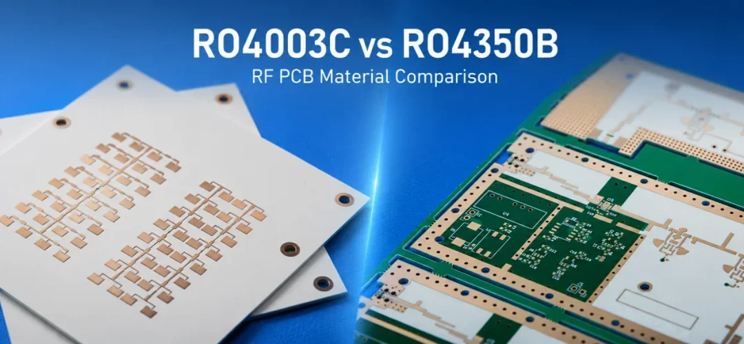
RO4003C vs RO4350B: Rogers Datasheet Values, LoPro Foil, and Stackup Choices
Figure 1. RO4003C vs RO4350B selection depends on...

Taconic RF-35 PCB Manufacturing Service — Prototype Through Volume Production
Figure 1. Taconic RF-35 PCBTaconic RF-35 is the workhorse...

Isola Astra MT77 PCB Manufacturing
Figure 1. Isola Astra MT77 PCB ManufacturingIsola Astra...

Custom Rogers RO4835 PCB Fabrication & Assembly Services
Figure 1. Rogers RO4835 PCBRogers RO4835 PCB is a...