
Back to blog
Selecting the Right PTFE Material for Your PCB

PCBs are the backbone of modern electronics, providing the essential interconnections between electronic components. While FR4 is the standard material for most PCBs due to its cost-effectiveness, PTFE PCBs, made from polytetrafluoroethylene (PTFE) substrates, offer exceptional properties that make them ideal for demanding applications. In this comprehensive guide, we will delve into the world of PTFE PCB technology, exploring its key properties, differences from FR4, typical applications, and more.
What is PTFE PCB?
PTFE PCB stands for Polytetrafluoroethylene Printed Circuit Board. It is a type of circuit board where the substrate material is made from PTFE, which is a synthetic fluoropolymer. PTFE is known for its excellent dielectric properties, chemical resistance, and thermal stability, making it ideal for high-frequency and high-performance applications. PTFE PCBs are commonly used in RF (Radio Frequency) and microwave applications due to their low dielectric constant and loss tangent, which allow for efficient signal transmission at high frequencies.
Properties of PTFE Circuit Board
PTFE PCBs offer a unique set of properties that set them apart from standard circuit boards:
- Chemical Resistance: PTFE retains its properties when exposed to oils, grease, and chemical reagents, making it suitable for harsh chemical environments.
- Low Temperature Durability: PTFE maintains flexibility and toughness even at extremely low temperatures, down to -196°C, making it suitable for cryogenic applications.
- Weatherability: PTFE stands up well to all weather conditions, including UV radiation, humidity, and temperature extremes, allowing for outdoor and unconditioned space use.
- Low Dielectric Losses: PTFE’s non-polar nature results in very low signal losses, especially at high frequencies, making it ideal for RF and high-frequency applications.
- Non-Stick Surface: PTFE’s molecular structure gives it a slippery, non-adhesive surface, preventing contamination and easing PCB assembly and cleaning.
- Moisture Resistance: With very low water absorption, PTFE boards withstand high humidity environments without electrical or physical degradation.
- Excellent Electrical Properties: PTFE offers high dielectric withstand voltage and volume resistivity, facilitating impedance control with its stable dielectric constant of approximately 2.0.
Composition of PTFE-Based Materials
Contrary to thick films like flexible polyimide, PTFE-based materials are composite substances crafted from PTFE alongside a mix of additives and fillers. The incorporation of specific additives and fillers is what distinguishes commercially available PTFE-based PCB materials for diverse applications. The principal component of these materials is a random PTFE matrix, with all additives encapsulated within the PTFE matrix, collectively determining the laminate’s electrical, mechanical, and thermal attributes.
Additives in PTFE-Based Materials
The incorporation of additives and fillers is a pivotal aspect of PTFE-based materials, enabling a broad spectrum of properties in commercial variants. There are two primary types of additives:
- Reinforcements: Primarily influencing mechanical behavior.
- Fillers: Affecting both mechanical and dielectric properties.
Reinforcements
- Glass-reinforced: Utilizes glass weave, which can be either standardized or random, offering strong rigidity against bending and ease of production.
- Ceramic-reinforced: Employs ceramic fibers to provide rigidity, tailoring the material’s properties.
- Unreinforced: Consists solely of a PTFE matrix without reinforcements, potentially containing ceramic particle fillers, and is highly pliable but challenging to work with during fabrication.
Fillers
Ceramic powders are the primary filler in commercial PTFE-based laminates, offering advantages over a woven or random glass matrix as reinforcement. Ceramics provide higher thermal conductivity than the PTFE base material and can modify dielectric properties to achieve higher Dk values, ideal for lower frequency RF systems.
Benefits of Ceramics in PTFE-Based Laminates
Ceramic-reinforced laminates are favored in RF systems due to several advantages over glass-reinforced variants. Ceramics offer:
- Higher thermal conductivity.
- Modification of dielectric properties for desired Dk values.
- Elimination of glass fiber weave issues, particularly critical at higher frequencies associated with mmWave systems.
- Broad engineering capabilities to tailor material properties, including thermal conductivity, CTE (Coefficient of Thermal Expansion) mismatch with copper, dielectric constant stability, and layer-to-layer misregistration reduction.
Selection of PTFE-Based Materials for RF Systems
For thinner dielectric layers, a ceramic-filled PTFE material is generally preferred, especially at very high frequencies where glass-reinforced materials should be avoided. While unreinforced materials can be acceptable, they are more challenging to handle during production due to their pliability. Leading vendors offering PTFE-based laminates with Dk values ranging from 3-10 include Rogers, Arlon, and Taconic.
For a more complete production review, use this article alongside circuit board material review and SMT assembly capability when checking stackup, assembly, or test requirements.
The Selection of PTFE Material
When selecting PTFE materials for specific applications, it is crucial to consider their dielectric constant (Dk) and dissipation factor (Df) to ensure optimal performance. The following table outlines various PTFE materials with their respective Dk and Df values, aiding in the selection of the most suitable material for specific design requirements.
| Material | Dk | Df |
|---|---|---|
| Arlon Diclad 880 | 2.17 | 0.0009 |
| Taconic TLY-5 A | 2.17 | 0.0009 |
| Taconic TLY-5 D | 2.20 | 0.0009 |
| Rogers RT5880 | 2.20 | 0.0009 |
| Arlon Diclad 527 | 2.40-2.60 | 0.0022 |
| Arlon AD255 | 2.55 | 0.0018 |
| Taconic TLX-8 | 2.51-2.59 | 0.0019 |
| Ultralam 2000 | 2.40-2.60 | 0.0019 |
| Arlon AD300 | 3.0 | 0.003 |
| Taconic RF-30 | 3.0 | 0.0014 |
| Rogers RO3003 | 3.00+/-0.04 | 0.0013 |
| Rogers RO3203 | 3.02+/-0.04 | 0.0016 |
| Arlon AD350 | 3.50 | 0.003 |
| Arlon AD350A | 3.50 | 0.003 |
| Taconic RF-35 | 3.50 | 0.0018 |
| Taconic RF-35P | 3.50 | 0.0025 |
| Rogers RO3035 | 3.50+-0.05 | 0.0017 |
| Arlon AD450 | 4.50 | 0.0035 |
| Taconic RF-45 | 4.50 | 0.0037 |
| Arlon AD600 | 6.15 | 0.003 |
| Taconic RF-60 | 6.15 | 0.0028 |
| Taconic RF-60A | 6.15 | 0.0028 |
| Rogers RO3006 | 6.15 | 0.002 |
| Rogers RO3206 | 6.15 | 0.0027 |
| TMM6 | 6.0 | 0.0023 |
| Arlon AD10 | 10.20 | 0.005 |
| Arlon AD1000 | 10.20 | 0.0023 |
| Arlon AR1000 | 10.00 | 0.003 |
| Taconic CER-10 | 10.00 | 0.0035 |
| Rogers TMM10 | 9.20+-0.23 | 0.0023 |
| Rogers TMM10i | 9.80+-0.245 | 0.002 |
| Rogers RO3010 | 10.20+-0.30 | 0.0023 |
| Rogers RO3210 | 10.20+-0.50 | 0.0027 |
The following recommendations are based on the provided Dk and Df values for each PTFE material:
- For materials with a Dk around 2.17-2.20, it is recommended to use TLY-5 A, TLY-5, or Diclad 880.
- Materials with a Dk around 2.55 should consider TLX-8 or Diclad 527, with a suggestion to upgrade AD255 to AD255A.
- A Dk around 3.0 suggests using RF-30 or AD300.
- For materials with a Dk around 3.50, RF-35 or AD350A are recommended.
- AD450 is recommended for materials with a Dk around 4.50.
- A Dk around 6.15 suggests using RF-60A.
- A Dk around 10 suggests using AD1000,CER-10.
PTFE PCB VS FR4 PCB: What’s the Difference? How to Choose?
PTFE (Polytetrafluoroethylene) and FR4 are two distinct materials used in circuit boards, each with its own set of characteristics and applications. Understanding the differences between them is crucial for selecting the most suitable material for your specific needs:
- Thermal and Chemical Resistance:
- PTFE: Offers superior thermal resistance, withstanding temperatures from -192°C up to over 250°C. It is also highly resistant to chemicals, making it suitable for harsh environments.
- FR4: While FR4 is a standard material and offers good thermal resistance up to 110°C, it is not as resistant to harsh chemicals as PTFE.
- Cost:
- PTFE: Generally comes at a higher cost, approximately 5-10 times that of FR4 boards.
- FR4: More cost-effective, making it a preferred choice for consumer electronics and other applications where cost is a primary consideration.
- Applications:
- PTFE: Ideal for industrial, military, aerospace, and other demanding applications where high heat or harsh chemicals are present. It is also suitable for cryogenic applications.
- FR4: Typically used in most general applications, including consumer electronics, due to its cost-effectiveness and suitability for standard operating conditions.
- Structural Integrity:
- PTFE: Maintains its structural integrity at high temperatures, making it suitable for applications requiring reliable performance in extreme conditions.
- FR4: Begins to lose its structural integrity above 110°C, limiting its use in high-temperature environments.
- Chemical Inertness:
- PTFE: Chemically inert, resisting nearly all industrial chemicals and solvents that would damage FR4.
- FR4: More susceptible to damage from certain chemicals compared to PTFE.
| Property | PTFE | FR4 |
|---|---|---|
| Temperature Range | -192°C to over 260°C | 110°C maximum |
| Dielectric Constant | 2.1 – 2.6 | 3.8 – 4.8 |
| Dielectric Strength | 300-500 V/mil | 150-200 V/mil |
| Water Absorption | 0.03-0.1% | 0.1% |
| Chemical Resistance | Excellent – resistant to nearly all chemicals | Moderate – damaged by some solvents/acids |
| Thermal Conductivity | 0.440 – 0.95 W/m/K | 0.3-0.6 W/m/K |
| Flexibility | Can be rigid or flexible | Rigid |
| Cost | 5-10x higher than FR4 | Low |
In summary, when choosing between PTFE and FR4 for your circuit board material, consider the operating conditions, including temperature limits and chemical exposure risks. If your application requires superior thermal and chemical resistance, especially in harsh environments, PTFE may be worth the higher cost. However, for standard applications where cost is a primary concern, FR4 remains a cost-effective and reliable option.
PTFE PCB Manufacturing and Assembly Provider – Highleap Electronic
Highleap Electronic is a leading provider of PTFE PCB manufacturing and assembly services, offering a comprehensive range of solutions for the design, development, and production of high-quality PTFE PCBs. Here are some key features of Highleap Electronic’s PTFE PCB manufacturing and assembly services:
- Advanced Manufacturing Technology: Highleap Electronic employs state-of-the-art manufacturing technology to ensure the highest quality and precision in PTFE PCB production.
- Experienced Engineers: Our team of experienced engineers is dedicated to providing innovative solutions and technical expertise throughout the PTFE PCB manufacturing process.
- Comprehensive Assembly Services: Highleap Electronic offers a wide range of assembly services for PTFE PCBs, including surface mount technology (SMT) assembly, through-hole assembly, and mixed-technology assembly, to meet the diverse needs of our customers.
- Quality Control: We have strict quality control measures in place to ensure that every PTFE PCB meets the highest standards of quality and reliability.
- Fast Turnaround Time: Highleap Electronic understands the importance of timely delivery. We offer fast turnaround times to meet the demanding schedules of our customers.
With our expertise and commitment to quality, Highleap Electronic is the ideal partner for customers who require high-quality PTFE PCBs for a wide range of applications.
Available Teflon PCB Models
There is a variety of Teflon PCB models available in the market, with suppliers including Rogers, Taconic, Taizhou Wangling, Nelco, and Arlon. While not all Rogers PCBs are Teflon PCBs, all PTFE PCBs are Teflon PCBs. Here are some of the Teflon PCB materials you can choose from (these are available at Highleap Electronic, and if you cannot find them here, you may not find them at other Teflon PCB manufacturers either):
| PTFE Laminates Suppliers | Material Series | PTFE Laminate Models |
|---|---|---|
| Arlon | Diclad | Diclad522, Diclad527, Diclad870, Diclad880 |
| Cuclad | Cuclad250GT, Cuclad250LX, Cuclad250GX, Cuclad233LX, Cuclad233GY, Cuclad217LX, Cuclad 217GY | |
| Isoclad | Isoclad933, Isoclad917 | |
| AD | AD250, AD255, AD255A, AD255C, AD255IM, AD255L, AD260A, AD270, AD350, AD350A, AD300, AD320, AD300C, AD300A, AD410, AD450, AD600, AD1000, AD10 | |
| other | AR1000, CLTE, CLTE-LC, CLTE-AT, CLTE-XT, TC350, TC600, EP-2 | |
| Nelco | NX9000 | NX9240, NX9245, NX9250, NX9255, NX9260, NX9294, NX9300, NX9320… |
| NY9000 | NY9208, NY9217, NY9220, NY9233… | |
| NH9000 | NH9294, NH9300, NH9320, NH9338, NH9348, NH9350… | |
| Rogers | RT5000 | RT5880, RT5870 |
| RT6000 | RT6002, RT6006 | |
| RT6010LM | ||
| RO3000 | RO3003, RO3006 | |
| RO3203, RO3210 | ||
| RO3010, RO3206 | ||
| RO3035HTC | ||
| Ultralam 2000 | Ultralam 2000 | |
| Ultralam 3000 | Ultralam 3850 | |
| Taizhou Wangling | F4B | F4B-2 |
| TF-1, 2 | TF-1, 2 | |
| TP-2 | TP-2 | |
| F4D-2 | F4D-2 | |
| TP-12 | TP-12 | |
| Taconic | TLX | TLX-0, TLX-6, TLX-7 |
| TLX-8, TLX-8-CL1, TLX-9 | ||
| TLY | TLY-3, TLY-5, TLY-5A | |
| TLC | TLC-27 | |
| TLC-30, TLC-32 | ||
| RF | RF-30 | |
| RF-60, RF-60A | ||
| RF-35, RF-35P | ||
| RF-45, RF-41 | ||
| RF-35A, RF-35A2 | ||
| TRF-45, TRF-43, TRF-41 | ||
| TF-2 | ||
| TLT | TLT-7, TLT-8, TLT-9,TLT-0, TLT-6 | |
| TL | TL-32, TL-35 | |
| TLF | TLF-35 | |
| TLK | TLK-8 | |
| TLA | TLA-6 | |
| RF | RF-35TC | |
| other | CER10, TSM-30 | |
| TLX-9 | TLX-9-0200 |
Among the Rogers Teflon PCB materials, the RT laminates (RT5000 series and RT6000 series) are mainly used for military and aerospace applications, while the RO3000 series is typically used for commercial applications.
Note: The popular Rogers series RO4000 does not belong to Teflon PCBs as the laminates are ceramics-based, not PTFE-based.
Advanced PCB High Performance Materials
PTFE (Polytetrafluoroethylene) is a remarkable material, known for its unique set of properties that make it ideal for a variety of applications, especially in the realm of printed circuit boards (PCBs). Its exceptional chemical resistance, low temperature durability, and non-stick surface are just a few of the qualities that set it apart from traditional PCB materials. As we delve deeper into the world of PCB materials, we will explore the advanced high-performance materials that push the boundaries of what is possible in modern electronics. Let’s take a closer look at some of these cutting-edge materials that are revolutionizing the PCB industry:
| Item | Material for PCB Prototype |
|---|---|
| General Tg FR4 | shengyi S1141, Kingboard KB6160A |
| High-Tg Halogen-free | shengyi S1170G Halogen-free TG170, TU-862 HF TG170 |
| Medium Tg Halogen-free | shengyi S1150G Halogen-free TG150 |
| High Halogen-free CTI | shengyi S1151G( CTI≥600V) |
| High CTI | shengyi S1600( CTI≥600V)Kingboard KB6160C |
| Special Material (High low temperature) | shengyi SH260 |
| High Tg FR4 | S1000-2, S1000-2M, IT180A |
| Ceramic Powder Filled High Frequency | Rogers4350, Rogers4003, Arlon25N, shengyi S7136 |
| PTFE High Frequency Material | Rogers, Taconic, Arlon, Taizhou wangling |
| High Frequency PCB PP | RO4450 0.1mm, shengyi Synamic6 |
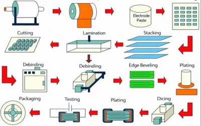
Teflon PCB Manufacturing: Key Considerations
A Teflon PCB, also known as a PTFE PCB, is a unique type of high-frequency printed circuit board that utilizes Polytetrafluoroethylene, better known as Teflon, a brand name by Dupont Corporation for its PTFE materials. Manufacturing Teflon circuit boards requires precision and attentiveness due to the distinct differences between Teflon and standard FR4 PCB materials. Here are the key manufacturing steps involved:
- Surface Preparation: Prepare the substrate’s surface for layer formation, marking, and metallization. Use tools that won’t damage the delicate laminate, such as sodium etchants or plasma gas recycling on the PTFE surface.
- Copper Plating: Carefully copper plate Teflon, a ceramic material with high dielectric properties. Use plated copper with high tensile strength on through-hole walls to reduce the likelihood of pad lifts and barrel cracks due to PTFE’s high Z-axis coefficient of thermal expansion.
- Application of Solder Mask: Apply the solder mask within 12 hours of etching the material. Eliminate any residual moisture by baking the PTFE laminates before applying the solder mask.
- Drilling: Use a high chip load to drill PTFE substrates covered with copper, eradicating fibers and PTFE tailing. Consider using ceramic-filled laminates for easier drilling.
- Handling and Storage: Handle PTFE laminates with care to prevent tearing or gouging. Store them at room temperature, away from sunlight, to prevent surface oxidation and contamination.
- Lamination: Unlike other materials, Teflon substrates don’t need oxide pretreatment. Laminate PTFE and copper films under high pressures without bonding films or pre-pegs. Occasionally, use bonding films or prepregs with a very low melting point to reduce processing temperatures. While PTFE-FR4 laminates are suitable for some applications, they require oxide pretreatment.
Overall, Teflon PCB manufacturing requires specialized processes and attention to detail to ensure high-quality circuit boards.
Conclusion
In summary, PTFE PCBs offer exceptional thermal and chemical resistance, making them ideal for demanding industrial, aerospace, medical, and military applications. They maintain reliability in harsh environments and are commonly used in process control, radar systems, and medical devices. PTFE’s unique properties, such as low dielectric losses and moisture resistance, contribute to its suitability for these applications. While PTFE comes at a higher cost compared to FR4, its performance in extreme conditions justifies the investment for critical applications.
When choosing between PTFE and FR4 for your circuit board material, consider the operating conditions and budget. PTFE’s superior thermal and chemical resistance make it ideal for applications requiring reliable performance in harsh environments, while FR4 remains a cost-effective option for standard applications. The selection should be based on the specific requirements of your application, ensuring that the chosen material can withstand the operating conditions and deliver the desired performance.

Related Articles
DBC Process for Ceramic Substrate Manufacturing
Learn how the DBC process bonds copper to ceramic and how process control affects quality reliability and thermal performance of ceramic substrates.
DBC Substrate Manufacturer for PCB Fabrication and PCBA
DBC substrate manufacturer support with PCB fabrication and PCBA services including sourcing coordination assembly and global delivery for power electronics.
DBC Substrate Prototype Builds and PCB Assembly Support
DBC substrate prototype builds for thermal and insulation validation with PCB fabrication and turnkey assembly support from sample to volume production.