
Key Steps in Microcontroller Circuit Board Design

Developing a microcontroller circuit board is a multifaceted process that blends advanced hardware design, embedded programming, and rigorous engineering principles. This guide provides an in-depth look at the entire journey—from initial planning and microcontroller selection to circuit design, PCB layout, programming, debugging, and production. By adhering to best practices throughout each phase, engineers can create reliable, high-performance circuit boards tailored to their application requirements.
1. Initial Planning and Defining Requirements
Project Specifications
Before diving into the design process, it is crucial to establish a clear set of project specifications that will guide every decision. These specifications should address the following key aspects:
Performance Requirements
- Computational Load: Define the complexity of tasks that the microcontroller will need to handle. For instance, applications involving high data processing or complex calculations may require a more powerful processor.
- Real-time Processing: If your project demands real-time processing (such as control systems or robotics), ensure that the microcontroller has sufficient response time to meet these requirements.
- Speed Requirements: Clearly identify if the system will need to process high-speed data streams. This could involve selecting interfaces and processing speeds capable of handling high bandwidth, such as video processing or large data handling.
Size and Form Factor
- Circuit Board Size Constraints: The physical dimensions of the board must be determined based on the space available within the overall system. For instance, if the circuit board will be integrated into an existing enclosure, it must fit within the predefined space. Efficient component placement is crucial to maximize the use of limited space.
- Form Factor: Choose the appropriate shape for the circuit board (e.g., rectangular, round, or custom shapes) depending on the application and compatibility with other components or systems.
Power Requirements
- Power Budget: Calculate the total power consumption of all components. Decide whether your design will be powered via a battery, USB, or other power sources. Battery-operated designs need particular attention to power management in order to maximize battery life. For devices powered by USB or AC power adapters, ensure the power supply matches the board’s voltage and current needs.
- Power Optimization: Consider ways to reduce power consumption, such as selecting low-power components, utilizing sleep modes, or optimizing the firmware to lower the overall energy usage.
Environmental Conditions
- Temperature Range: Specify the temperature extremes the circuit board will operate in. This will influence component selection, as different components have varying tolerances for high and low temperatures. If the board will operate in industrial or automotive environments, consider selecting components rated for extreme temperature conditions.
- Humidity and Corrosion: Consider the environmental exposure, such as high humidity, dust, or corrosive conditions. In such cases, select components that are suitable for harsh environments or employ protective coatings to safeguard the board.
- Vibration and Shock: For systems operating in environments with mechanical vibration or shock (e.g., automotive or industrial applications), consider reinforcing the physical structure of the PCB and selecting components with high durability against these factors.
Cost Limitations
- Component Costs: Select components that meet performance requirements while staying within budget. Striking a balance between performance and cost is essential to avoid unnecessary expenditure.
- Manufacturing Costs: Take into account the cost of manufacturing the PCB, including PCB fabrication, soldering, and assembly. Consider the unit cost for large-scale production and optimize the design for efficient manufacturing.
- Labor Costs: Factor in the cost of time for designing, testing, and assembling the PCB. Ensure that the project is completed within the time frame to avoid additional labor costs.
These project specifications will guide the entire design process and ensure that each decision aligns with the overall goals and requirements of the project. By defining these parameters at the outset, you can avoid costly revisions and create a more efficient, cost-effective design.

2. Microcontroller Selection
Evaluating Microcontroller Options
Choosing the right microcontroller (MCU) is crucial for the success of your circuit board. When evaluating potential options, it’s essential to consider several key criteria to ensure the selected MCU meets the performance and functional requirements of your project. Below are the main factors to evaluate:
-
Processing Speed: Evaluate the clock speed and processing capabilities required to meet real-time demands or performance-intensive tasks. If your project requires high computational performance, select a microcontroller with a higher processing speed.
-
Memory Capacity: Consider the memory requirements for your application. Flash memory is used for storing the program, while RAM is necessary for data processing. Ensure the MCU has enough storage capacity for your program and runtime data.
-
Peripheral Availability: The number and types of I/O pins are critical. Make sure the MCU has enough I/O pins to connect with external devices, sensors, or peripherals. Common interfaces like UART, SPI, and I²C should be available if needed for communication between devices.
-
Power Consumption: For battery-powered designs, low power usage is a must. Look for MCUs that support power-saving features such as sleep modes and efficient voltage regulation to ensure long battery life.
-
Package and Footprint: The package type (e.g., QFN, DIP, BGA) affects how the microcontroller will fit on the PCB and its ease of assembly. The physical size of the MCU should align with the available space on the circuit board.
-
Cost and Supply Chain: The cost of the microcontroller should fit within your project budget. Additionally, consider the availability of the MCU and its long-term supply to avoid disruptions during mass production.
Microcontroller Selection Criteria
To help guide your decision, here’s a summary table outlining important selection criteria for various microcontroller options:

Building a Selection Matrix
To further assist in selecting the best microcontroller, develop a comparison matrix that lists popular microcontroller families such as ATmega, STM32, PIC, and ESP32, alongside their key characteristics. Assign weights to each criterion based on its importance to your project, and use the matrix to evaluate and select the most suitable microcontroller for your application.
Here’s an example table of popular microcontroller families and their common applications:

3. Circuit Design and Component Integration
Creating the Schematic
Once you have selected the microcontroller for your project, the next step is to design a comprehensive schematic. This schematic serves as the blueprint for your circuit board, detailing how all components are connected and how the system will function. The schematic is typically divided into several key sections:
Power Supply Circuitry
-
Voltage Regulators: One of the first considerations is selecting the appropriate voltage regulators. You’ll typically choose between three options:
- Linear Regulators: These are simple to design but tend to waste energy as heat, so they are best used in low-power applications.
- Switching Regulators: These are more efficient than linear regulators and are suitable for higher power applications, as they convert excess voltage into usable power.
- Low-Dropout (LDO) Regulators: These are a good choice when you need to maintain a constant voltage even with a small difference between input and output voltages. They are commonly used in battery-powered designs.
Choosing the correct regulator type is important for balancing power efficiency, heat generation, and system complexity.
-
Protection Mechanisms: To ensure the safety and longevity of your design, include the following protection features:
- Reverse Polarity Protection: Prevents damage if the power supply is connected incorrectly.
- Overcurrent Protection: Protects the circuit from excessive current, which could damage components.
- ESD Protection: Prevents electrostatic discharge from damaging sensitive components, especially during handling or operation.
Critical Signal Circuits
-
Reset Circuits: These are essential for ensuring the microcontroller initializes properly upon power-up. Include:
- Power-On Reset: Automatically resets the microcontroller when the system is powered on.
- Manual Reset: Allows the user to manually reset the microcontroller if necessary.
- Supervisory ICs: These monitor the power supply and ensure the system stays within safe operating voltage limits.
-
Clock Sources: A reliable clock source is crucial for the accurate operation of your microcontroller and other timing-related tasks:
- Crystal Oscillators: These provide the clock signal for the microcontroller. When selecting a crystal, ensure it meets the frequency requirements and is stable in your operating environment.
- Load Capacitors: These are necessary for tuning the oscillator and ensuring stable operation. Keep trace lengths between the crystal and capacitors as short as possible to minimize noise and interference.
Peripheral Interface Circuits
-
Communication Interfaces: Different communication protocols are used depending on the peripherals you plan to connect:
- UART (Universal Asynchronous Receiver-Transmitter): Commonly used for debugging and serial communication with other systems.
- SPI (Serial Peripheral Interface): A faster interface for connecting sensors, displays, or other peripherals that require high-speed data exchange.
- I²C (Inter-Integrated Circuit): A popular protocol for connecting multiple peripherals with just two wires (SDA and SCL), allowing for efficient communication in complex systems.
-
Analog Interfaces: Many systems require analog inputs for sensors or other real-world signals. Design ADC input circuits with careful attention to filtering and signal conditioning:
- Filtering: Use low-pass filters to remove high-frequency noise that could distort the signal.
- Signal Conditioning: Ensure that the analog signal is within the correct voltage range for the ADC input and that the signal is stable for accurate measurement.
Component Selection and Data Sheets
Once the schematic is complete, it’s time to choose the appropriate components. To do this, refer to the manufacturer datasheets for each component. These datasheets provide important details, such as:
- Electrical Characteristics: Ensure the component’s voltage, current, and power ratings align with your circuit’s needs.
- Thermal Requirements: Some components may require heat sinks or other cooling measures to prevent overheating, especially in high-power applications.
- Tolerance and Noise Specifications: Pay close attention to tolerance levels (especially for resistors and capacitors) and noise specifications, as these can impact the accuracy and stability of the circuit.
- Environmental Ratings: If your circuit will be used in harsh environments (high temperatures, humidity, etc.), ensure the components are rated for such conditions.
Careful component selection is essential for ensuring that your circuit operates reliably across all conditions, minimizing the risk of failure or malfunction in your final product.

4. Microcontroller PCB Layout and Manufacturing
Layout Strategy and Best Practices
A well-executed PCB layout is essential to the performance, reliability, and manufacturability of your circuit board. To ensure signal integrity, thermal stability, and ease of manufacturing, consider the following best practices during the design phase:
- Component Placement: Position critical components like the crystal oscillator and bypass capacitors as close as possible to the microcontroller’s power pins to reduce noise and ensure stable operation. Similarly, power supply components and voltage regulators should be placed strategically to optimize heat dissipation, and heat sinks should be used when necessary.
- Connector Placement: Ensure that connectors are placed along the edges of the PCB for easy accessibility during assembly and integration. This positioning also ensures that the board can be quickly tested and deployed.
Layer Stack-Up for Multi-Layer Designs
For most microcontroller boards, a 4-layer stack-up is typical. This stack-up ensures that power distribution is stable and reduces noise interference. A typical 4-layer PCB stack-up includes:
- Top Layer: This layer is dedicated to component placement and primary signal routing, ensuring that all active components are properly positioned.
- Inner Layers:
- Inner Layer 1 (Ground Plane): A solid, continuous ground plane helps to reduce noise and ensures stable reference points for the signal return paths.
- Inner Layer 2 (Power Plane): This dedicated power plane ensures the voltage rails are evenly distributed to various components, helping stabilize power delivery and reducing voltage fluctuations.
- Bottom Layer: Used for additional routing, this layer supports the less critical signals and helps with routing complex traces while maintaining efficient use of space.
Routing Techniques for Optimal Performance
Proper routing of traces is essential to maintaining signal integrity and ensuring reliable operation. Pay attention to the following aspects:
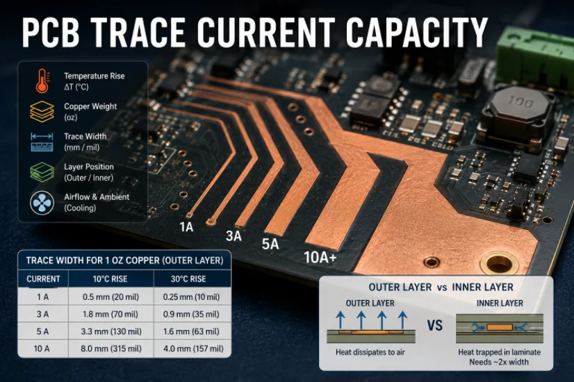
- Trace Width and Spacing: It’s crucial to follow design rules for trace width based on the current carrying requirements. For example, traces carrying high current need to be wider to minimize resistance and avoid excessive heat generation. Using online calculators or design tools can help determine the exact width of traces based on the expected current.
- Grounding and Decoupling: Continuous ground planes should be used to reduce electromagnetic interference (EMI) and ensure stable power delivery. Decoupling capacitors should be strategically placed near the power supply pins to filter out high-frequency noise and stabilize the voltage levels.
- Signal Integrity: For high-speed digital signals, route these traces with controlled impedance. Ensure analog and digital signals are physically separated on the PCB to minimize crosstalk and interference between them.
Fabrication Considerations for Precision
Modern PCB manufacturing involves various advanced techniques to ensure tight tolerances and high-quality performance. To ensure the success of your PCB design during production, consider these steps:
- File Preparation: Ensure all design files (schematics, PCB layout, BOM, etc.) are accurate and reviewed before submission to the manufacturer. This helps minimize errors and issues during production.
- Manufacturing Process: Communicate directly with your PCB manufacturer about the specifications, including the number of layers, material types, trace widths, and hole sizes. Double-check these parameters to ensure that the boards meet the required standards and will function as expected.
Advanced Manufacturing and Design Insights
For further insights into advanced PCB design and manufacturing techniques, it is essential to stay updated with the latest processes and tools in the industry. Automated optical inspection (AOI), laser direct imaging (LDI), and high-density interconnect (HDI) methods are some of the modern technologies used to ensure the precision and quality of the fabricated boards. By understanding and applying these manufacturing advancements, you can achieve a high-quality PCB that meets your design goals.
For more detailed information on PCB design and assembly, visit the following resources on our website:
https://hilelectronic.com/pcb-design/
https://hilelectronic.com/pcb-assembly/
https://hilelectronic.com/electronic-manufacturing-service/

5. Programming, Debugging, and Firmware Development
Firmware Architecture
Develop firmware that meets the application’s requirements for real-time processing and peripheral management. Key aspects include:
- Initialization Routines: Ensure that all peripherals (ADC, timers, communication interfaces) are properly initialized.
- Interrupt Handling: Implement robust interrupt routines to manage critical functions such as data acquisition and real-time processing.
- Modular Code Structure: Use a modular approach to separate hardware control, data processing, and user interface functions. This structure simplifies debugging and future modifications.
Programming Interfaces and Debug Tools
Common programming methods include In-System Programming (ISP), JTAG, and SWD. Choose the interface based on the microcontroller’s capabilities and available development tools. Debugging is facilitated through hardware debuggers, serial communication for printf-style debugging, and LED indicators for real-time status monitoring.
Calibration and Testing Routines
Incorporate calibration routines to adjust for component tolerances, thermal drift, and non-linearities in analog circuitry. Software routines should periodically verify system parameters and alert the user if recalibration is necessary. Robust testing and debugging protocols, including the use of logic analyzers and oscilloscopes, are essential to validate firmware performance.
6. Testing, Verification, and Production Considerations
Comprehensive Testing Strategy
A thorough testing strategy is essential to ensure the final circuit board meets all design specifications. Testing procedures include:
- Functional Testing: Verify that all circuits (power, signal, communication) operate as intended. Use multimeters, oscilloscopes, and logic analyzers to capture and analyze signals.
- Stress Testing: Subject the board to thermal cycling, vibration, and load testing to ensure reliable operation under extreme conditions.
- Interface Testing: Validate communication protocols (UART, SPI, I²C) and peripheral performance, ensuring that all connected devices operate without interference.
Documentation and Quality Assurance
Detailed documentation supports both manufacturing and future troubleshooting. Essential documents include:
- Design Files: Complete schematics, PCB layout files, and bill of materials (BOM).
- Test Procedures: Step-by-step guidelines for functional and environmental testing.
- Assembly Instructions: Documentation of component placement, soldering profiles, and quality control measures.
Quality assurance practices, such as regular design reviews and iterative testing, help minimize production errors and ensure consistent performance across production runs.
Production and Assembly
For low-volume production, hand assembly or manual soldering may be acceptable, but for larger volumes, automated pick-and-place assembly is preferred. Consider the following:
- Component Availability: Ensure that all parts are readily available and meet the necessary quality standards.
- Cost Management: Evaluate production costs and consider economies of scale.
- Manufacturing Tolerances: Work with reputable PCB manufacturers to guarantee that production tolerances are met consistently.
Conclusion
Creating a microcontroller-based circuit board requires meticulous planning, careful component selection, sophisticated circuit design, and rigorous testing. By considering performance, environmental, and cost constraints from the outset, engineers can design boards that not only meet immediate project needs but also provide a reliable platform for future expansion. A robust PCB design, combined with optimized firmware and effective debugging techniques, is the cornerstone of successful embedded systems. Following best practices in design and manufacturing—supported by thorough documentation and quality control—ensures that the final product operates reliably in real-world applications.
This guide outlines a systematic approach to microcontroller circuit board design that is both comprehensive and professional. By integrating proven engineering principles with state-of-the-art PCB manufacturing techniques, you can achieve a design that excels in performance, reliability, and cost-effectiveness.
Frequently Asked Questions
Q1: What are the key factors in selecting a microcontroller?
A: The selection should focus on processing speed, memory capacity, peripheral availability, power consumption, cost, and package type. Consider future expansion and application-specific requirements.
Q2: How do I determine the best power supply configuration for my board?
A: Assess the input voltage range, current needs, efficiency requirements, and thermal constraints. Compare linear regulators, switching regulators, and LDOs based on these parameters.
Q3: What PCB design practices ensure reliable operation?
A: Essential practices include proper component placement, effective grounding, use of decoupling capacitors, controlled trace routing, and adherence to design rules for thermal management and EMI reduction.
Q4: How can I make my board easier to manufacture?
A: Use standard component sizes, maintain adequate spacing, include fiducial markers, adhere to standard PCB thicknesses, and design for panel assembly with clear test points.
Q5: What debugging approaches are recommended for microcontroller boards?
A: Utilize hardware debuggers (JTAG/SWD), serial communication for debugging output, integrated LED indicators, and test points for current and voltage measurements. Use logic analyzers for detailed signal analysis.
Get a Free PCB & PCBA Quote

Recommended Posts

PCB Current Calculator: Sizing Trace Width and Vias with the IPC-2221 Formula
Figure 1. Pcb Current Calculator reference image for PCB...
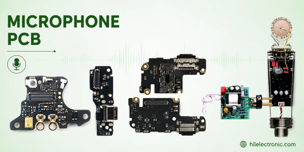
Microphone PCB Design: How the Board Itself Shapes Your Audio Quality
Figure 1. Microphone Pcb reference image for PCB...
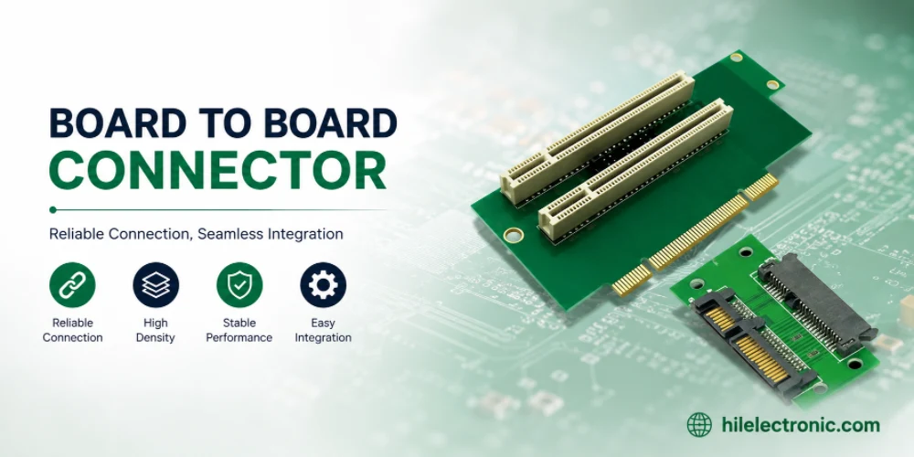
Board-to-Board Connector: Types, Specifications, and How to Select One
Figure 1. Board To Board Connector reference image for PCB...
PCB Trace Width Calculator: How to Size Traces for Current, Voltage Drop, and Impedance
Figure 1. A PCB trace width calculator is a starting point...
How to get a quote for PCBs
Let us run DFM/DFA analysis for you and get back to you with a report.
You can upload your files securely through our website.
We require the following information in order to give you a quote:
-
- Gerber, ODB++, or .pcb, spec.
- BOM list if you require assembly
- Quantity
- Turn time
In addition to PCB manufacturing, we offer a comprehensive range of electronic services, including PCB design, PCBA (Printed Circuit Board Assembly), and turnkey solutions. Whether you need help with prototyping, design verification, component sourcing, or mass production, we provide end-to-end support to ensure your project’s success. For PCBA services, please provide your BOM (Bill of Materials) and any specific assembly instructions. We also offer DFM/DFA analysis to optimize your designs for manufacturability and assembly, ensuring a smooth production process.