
Isola I Tera MT40 Prepreg Properties and PCB Applications

Isola I Tera MT40 prepreg is a low loss high frequency PCB material used in 5G RF and high speed digital designs above 5 GHz. It offers lower dielectric loss and more stable Dk performance than standard FR4 while remaining compatible with multilayer PCB fabrication processes. Highleap Electronics fabricates I Tera MT40 PCBs with validated stackup design and process control to ensure consistent high frequency performance.
Table of Contents
- What Is Isola I-Tera MT40 Prepreg?
- Key Electrical Properties and Frequency Behavior
- When Does Your Design Actually Need I-Tera MT40?
- Prepreg Styles and Stackup Engineering
- I-Tera MT40 vs. Competing Low-Loss Laminates
- Copper Foil Selection for I-Tera Signal Layers
- Fabrication Process Requirements
- Highleap Electronics I-Tera MT40 PCB Capabilities
1. What Is Isola I-Tera MT40 Prepreg?
Isola I-Tera MT40 is a low-loss, high-speed thermoset laminate and prepreg system engineered for PCB applications above 5 GHz. Unlike PTFE-based materials (Rogers RT/duroid, Taconic TLY), I-Tera MT40 is a glass-fiber reinforced thermoset that processes on standard FR4-class equipment with targeted modifications — making it faster to fabricate, more compatible with multilayer hybrid stackups, and more cost-effective than pure PTFE solutions, while still delivering the Dk stability and low Df performance that RF-grade designs require.
At Highleap Electronics, I-Tera MT40 is a production-qualified material processed under validated lamination press profiles specifically characterized for its resin chemistry. For a full overview of our high frequency PCB fabrication services, including I-Tera alongside Rogers, Taconic, and Megtron platforms, see our capabilities page.
2. Key Electrical Properties and Frequency Behavior
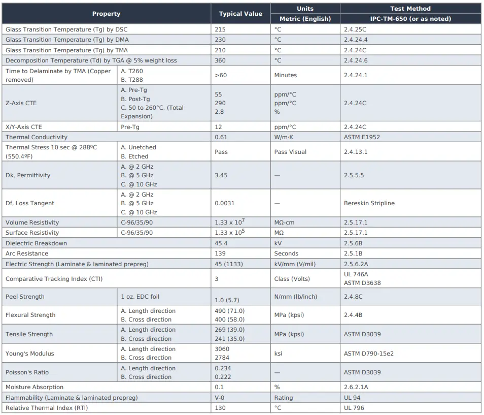
Dk and Df are not static constants — they shift with frequency, temperature, and moisture content. I-Tera MT40 is engineered for minimal property drift across the operating range:
| Property | Value | Condition |
|---|---|---|
| Dielectric Constant (Dk) | 3.45 ±0.05 | 10 GHz, IPC-TM-650 2.5.5.5c |
| Dissipation Factor (Df) | 0.0031 | 10 GHz, IPC-TM-650 2.5.5.5c |
| Glass Transition Temp (Tg) | 185°C (DSC) | IPC-TM-650 2.4.25 |
| Thermal Decomposition (Td) | 340°C | IPC-TM-650 2.4.24 |
| Z-axis CTE (50–260°C) | 2.8% | IPC-TM-650 2.4.24 |
| Practical Frequency Range | DC – 25+ GHz | Insertion loss controlled |
3. When Does Your Design Actually Need I-Tera MT40?
3.1 The Frequency Threshold: Where FR4 Stops Working
Standard FR4 has a dissipation factor of 0.018–0.025 at 1 GHz — 6–8× higher than I-Tera MT40. The practical threshold where standard glass-fiber laminates become a liability for controlled impedance traces is approximately 3 GHz. Above 5 GHz, FR4’s insertion loss on RF signal layers is unacceptable for any antenna, filter, or transmission line design. Understanding these high frequency material boundaries is the starting point for every RF design.
I-Tera MT40 is correctly specified when your design meets any of the following criteria:
- RF signal traces above 5 GHz — microstrip, stripline, or CPW carrying RF content at 5 GHz and above
- SerDes interfaces above 25 Gbps — DDR5, PCIe Gen 5, 100G/400G Ethernet where total channel insertion loss budget is tight
- Production impedance tolerance ±5% or tighter — where Dk uniformity determines yield, not just mean performance
- 5G base station and backhaul hardware — where insertion loss specifications are contractual and production consistency is OEM-verified
- Cost-competitive alternative to PTFE — designs that specify Rogers RO4350B but where I-Tera MT40 meets the loss budget and offers better supply chain availability
3.2 When I-Tera MT40 Is the Wrong Choice
Above 25 GHz, I-Tera MT40’s Df of 0.0031 becomes the insertion loss bottleneck. For 5G mmWave array modules, 77 GHz automotive radar, and Ka/Ku-band satellite hardware, PTFE-based laminates (Rogers RO3003, RT/duroid 5880) are required to meet system insertion loss budgets. For pure digital logic below 3 GHz, high-Tg FR4 is sufficient and significantly cheaper.
4. Prepreg Styles and Stackup Engineering
I-Tera MT40 prepreg is available in multiple glass styles (106, 1080, 2116, 3313), each with different resin content and cured thickness. The prepreg style affects the Dk contribution of the bond layer and the impedance of adjacent traces. For hybrid I-Tera/FR4 builds, using style 3313 over 2116 at the RF bond interface reduces dielectric discontinuity — a detail that directly affects controlled impedance accuracy at the lamination interface above 15 GHz. An experienced manufacturer specifies the correct style based on your target dielectric thickness and impedance model — not the cheapest available option.
5. I-Tera MT40 vs. Competing Low-Loss Laminates
| Material | Dk @ 10 GHz | Df @ 10 GHz | Best Application Range |
|---|---|---|---|
| Isola I-Tera MT40 | 3.45 | 0.0031 | 5–25 GHz: 5G, SerDes, RF amplifier |
| Panasonic Megtron 6 | 3.40 | 0.0038 | DC–25 GHz: high-speed digital convergence |
| Panasonic Megtron 7 | 3.37 | 0.0030 | DC–30+ GHz: next-gen mmWave SerDes |
| Rogers RO4350B | 3.48 | 0.0037 | DC–40 GHz: hybrid stackups, 5G antenna |
| Rogers RO3003 | 3.00 | 0.0010 | DC–77+ GHz: automotive radar, satellite |
The full material comparison framework — including supply chain geography, process complexity, and cost per layer — is covered in our PCB laminate material selection guide.
6. Copper Foil Selection for I-Tera Signal Layers
Selecting I-Tera MT40 for its low Df and pairing it with standard electrodeposited (ED) copper is one of the most common performance failures in RF PCB design. Above 5 GHz, the skin effect concentrates current in the outer microns of the conductor — if Rz roughness exceeds skin depth, effective conductor resistance increases and insertion loss climbs. Highleap specifies VLP copper as the default for I-Tera MT40 signal layers above 10 GHz. If your RFQ does not explicitly call out copper foil type, confirm with your manufacturer before approving the stackup.
7. Fabrication Process Requirements for I-Tera MT40
I-Tera MT40 processes on FR4-class equipment with specific modifications. Unlike PTFE, it does not require plasma desmear. However, a factory running I-Tera through an unmodified FR4 press program will produce boards with suboptimal Dk uniformity and potentially incomplete cure — variance that appears as impedance drift across production panels. Critical requirements are: validated cure profile for I-Tera resin chemistry; VLP/RTF copper on RF layers; material-specific etch compensation; and 100% TDR coupon measurement per panel.
For hybrid I-Tera/FR4 stackups, CTE mismatch between the I-Tera outer layers and FR4 inner cores requires anisotropic artwork scaling in CAM to maintain registration. Factories without validated CTE compensation data for this combination produce registration errors that appear only at high layer counts or fine-pitch via structures. This process detail is one reason we recommend reviewing our PCB manufacturing process overview before selecting a fabrication partner for hybrid builds.
For designs incorporating HDI via structures within I-Tera layers, blind and buried via processing must account for the material’s specific drill parameters and post-drill treatment — different from standard FR4 HDI builds.
8. Highleap Electronics: Isola I-Tera MT40 PCB Fabrication and Assembly
Highleap Electronics maintains production-qualified processes for Isola I-Tera MT40 prepreg. Standard service deliverables for every I-Tera program:
- DFM Review: I-Tera-specific review covering prepreg style, copper foil, CTE compensation, and impedance model validation — returned with every quote
- Material Traceability: Isola lot certificate with every production order — required for defense, aerospace, and medical programs
- 100% TDR Measurement: Physical impedance coupon data report in every shipment — not a pass/fail certificate
- VNA Testing: S21/S11 S-parameter data available for loss-critical applications above 10 GHz
- Cross-Section Microsection: First-article and production sampling — bond interface quality, via plating thickness, etch geometry
- Integrated Assembly: Turnkey PCB assembly with I-Tera-specific reflow profiles following fabrication
Ready to fabricate on Isola I-Tera MT40? Send your Gerbers and stackup requirements — we return a DFM review, material recommendation, and fabrication quote within 24 hours.
Frequently Asked Questions
Neither is universally better — the right choice depends on operating frequency, insertion loss budget, and supply chain requirements. RO4350B is preferred for hybrid stackups bonded with RO4450F prepreg and for designs above 20 GHz. I-Tera MT40 offers a competitive loss profile for 5G sub-6 GHz and backhaul with a larger global distribution network. Contact Highleap for a recommendation based on your specific stackup.
Yes. Hybrid I-Tera MT40 / high-Tg FR4 stackups are a cost-effective architecture for boards with mixed RF and digital content. Bond layer prepreg style and CTE compensation are critical variables that must be managed by a qualified fabricator. Highleap Electronics has validated press profiles for I-Tera/FR4 hybrid builds in production.
Yes. Standard I-Tera MT40 core thicknesses and prepreg styles are maintained in our inventory for prototype and production volumes. Fast-turnaround fabrication on I-Tera MT40 hybrid stackups is achievable in 7–10 business days for stocked configurations.

Recommended Posts
LED Parking Lot Light PCB Manufacturing & Assembly by Highleap Electronics
Figure 1. LED parking lot light PCB production and...
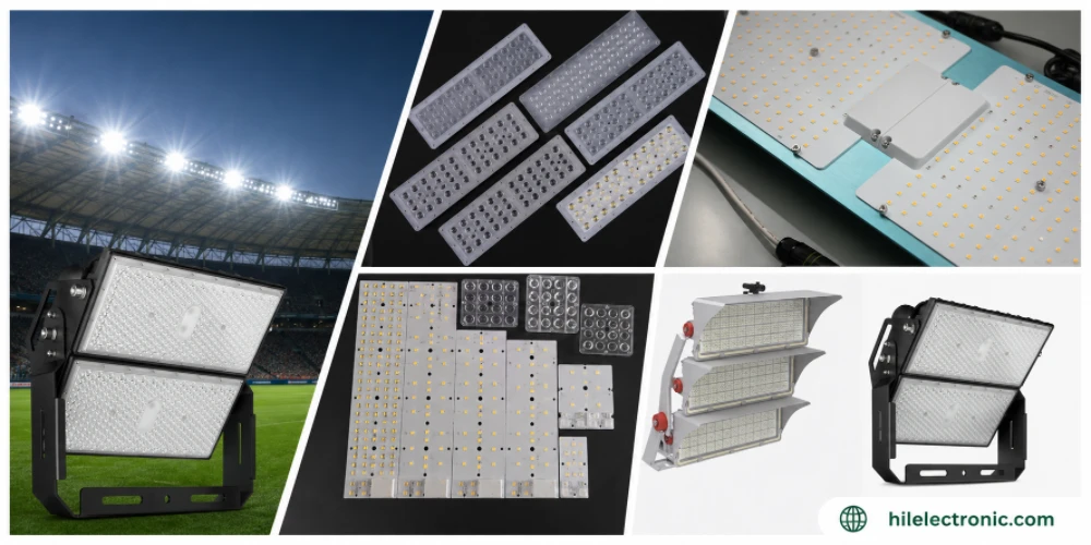
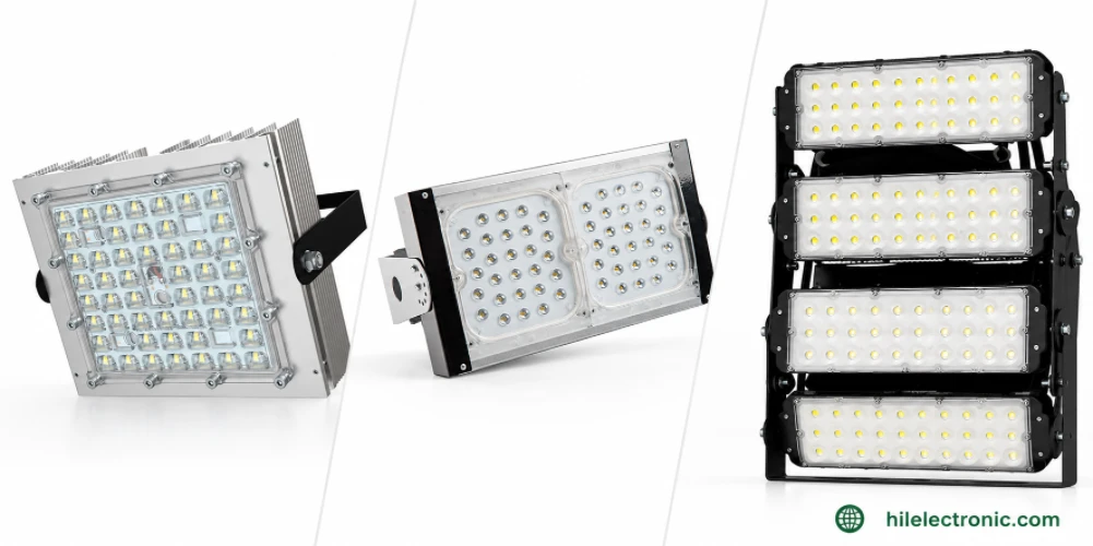
LED Stadium Light PCB Manufacturing — Very-High-Power Engines & Flicker-Free Drivers
Figure 1. LED stadium light PCB production and assembly...

LED Tunnel Light PCB Manufacturing — High-Reliability Engines & Drivers
Figure 1. LED tunnel light PCB production and assembly...
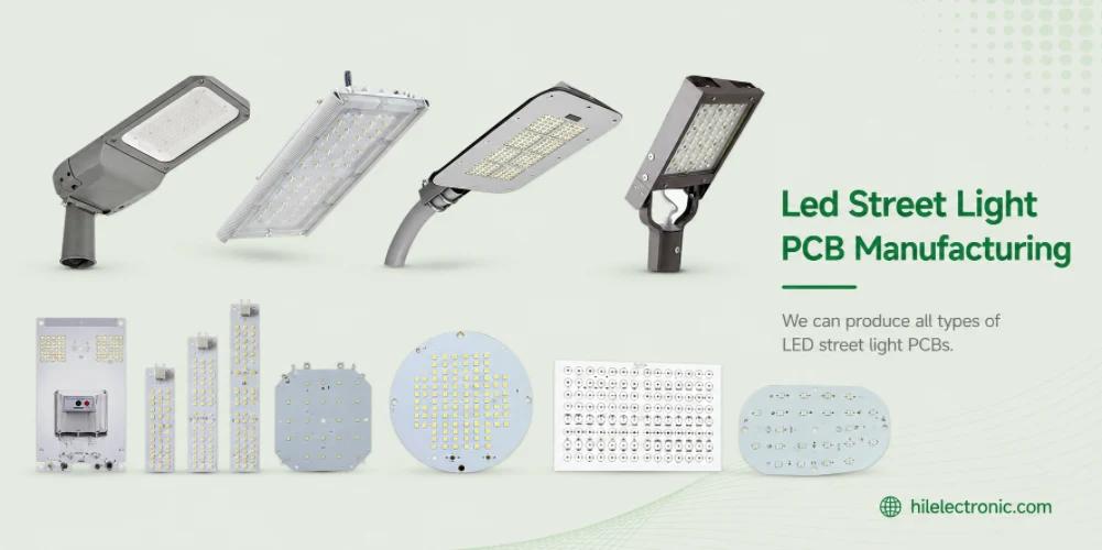
LED Street Light PCB Manufacturing & Assembly by Highleap Electronics
Figure 1. LED street light PCB production and assembly...
How to get a quote for PCBs
Let us run DFM/DFA analysis for you and get back to you with a report.
You can upload your files securely through our website.
We require the following information in order to give you a quote:
-
- Gerber, ODB++, or .pcb, spec.
- BOM list if you require assembly
- Quantity
- Turn time