
External Hard Drive Enclosure PCB Manufacturing & Assembly
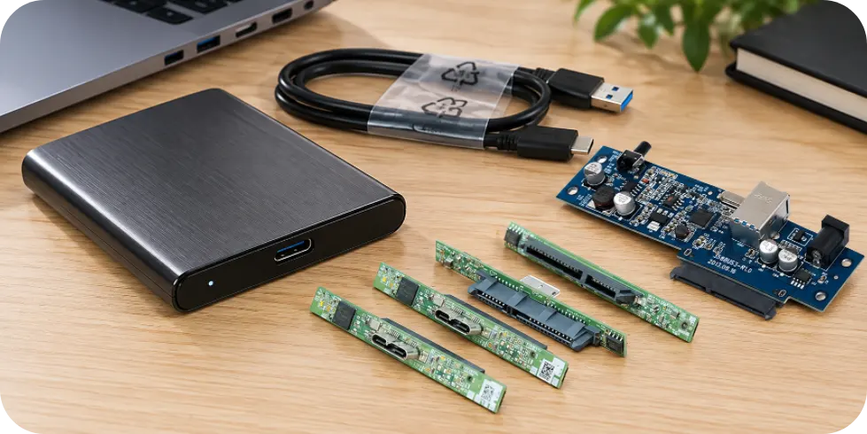

A hard drive enclosure PCB can pass a USB detection test on the bench and still fail when a real HDD spins up. A second board may have sound solder joints but fail to fit the enclosure because its SATA connector sits at the wrong height.
For an external hard drive enclosure PCB, production readiness therefore involves more than a working bridge circuit. The board must match the intended drive, host interface, power source and mechanical assembly.
Highleap Electronics fabricates and assembles customer-released bridge boards, power PCBAs and drive-interface assemblies through its electronic manufacturing services. Approved component procurement, SMT/through-hole assembly and customer-defined tests can be included according to the released files and agreed manufacturing scope.
Which HDD Enclosure PCB Assemblies Are You Ordering?
Three products can all be described as an HDD enclosure, yet involve very different PCB assembly orders:
- Portable 2.5-inch USB enclosure: Often a compact bridge PCBA with the USB connector, SATA receptacle and local power circuitry. Its production requirements depend on connector position and the host-power budget.
- Powered 3.5-inch enclosure: May combine the bridge and power stage on one board or use a separate power PCBA. The RFQ must account for the external adapter, drive supply rails and DC-input connector.
- Dual-bay dock or multi-bay DAS: Can involve a controller board, drive-connector/backplane PCB, shared power distribution and a smaller interface or indicator board. These functions can also be integrated into fewer boards.
For multi-board products, the manufacturer needs the quantity and revision of each PCBA per finished unit, plus any cables or interconnects included in the order. A bridge-board Gerber file on its own does not describe a complete powered enclosure.
Also distinguish the enclosure electronics from the hard drive PCB attached to the HDD itself. They are different assemblies with different functions and sourcing requirements.
USB-to-SATA Bridge PCB: Parts and Firmware That Must Stay Matched
The USB-to-SATA bridge controls how the attached drive appears to the host. Two devices with similar descriptions—or even compatible footprints—may differ in firmware, configuration storage and supported functions.
Before repeat assembly, lock together the bridge part number, approved alternatives, firmware or configuration file (if needed), and the hardware revision. A bridge substitution is not just a component-purchasing decision.
Don’t specify bridge performance by the USB socket alone
A USB-C receptacle does not establish USB data speed, USB Power Delivery or UASP support. Those depend on the controller, electrical design, firmware and host. For a USB-C hard drive enclosure PCB, document the actual USB implementation separately from the connector type.
What to hold constant during production
- Bridge device: the exact approved controller and any configuration memory.
- Programming: the released image, expected USB identity and programming procedure, where applicable.
- Associated components: specified oscillators, memory and power-stage devices governed by electronic component sourcing approvals.
- Acceptance: the expected enumeration and storage behavior with the agreed reference setup.
If the wrong device identity appears or the expected storage behavior is missing, configuration and firmware should be checked before replacing correctly assembled components. Not every enclosure requires factory programming.
HDD Enclosure Power Boards: Test the Drive at Spin-Up
A voltage check with no disk installed cannot establish whether the enclosure will start its intended HDD. Many 2.5-inch SATA drives use a 5V supply and may operate from USB when the host and cable can supply enough power. Conventional 3.5-inch SATA drives typically need both 5V and 12V, usually from an external source.
The supported-drive list and drive datasheets—not the enclosure’s marketing name—determine the power budget.
Measure where the HDD receives power
For a 3.5-inch HDD enclosure power board, the input adapter, rail map, connector ratings, protection devices and startup load need to be defined. The useful measurement point is the drive connector during spin-up, not only the regulator output without a load.
A marginal DC jack, incorrect MOSFET or resistive copper path can cause a reset only when the motor starts. Multi-bay products also require the intended simultaneous or sequenced startup behavior to be specified rather than assumed.
Two operating conditions need different checks
- Startup: Use the approved reference drive or defined load to confirm acceptable rail behavior while the HDD starts and the bridge remains active.
- Sustained access: Run the agreed read/write workload to screen for instability that appears only after the drive is operating.
For bus-powered models, include the specified host or supply and cable. For externally powered models, include the approved adapter. Test duration and pass/fail limits must be agreed before fixtures are finalized.
SATA Connector Alignment: The First-Article Check That Matters
A correctly soldered SATA connector can still be incorrectly positioned inside the enclosure. The receptacle, PCB mounting holes and housing guides must refer to compatible mechanical datums. Otherwise, inserting the HDD can bend the PCB or load the connector.
Check the assembled board with the intended drive
For the first article, use the drive and enclosure—or a representative fixture—to verify:
- Mating geometry: SATA connector height, insertion axis and drive seating.
- Board support: mounting posts, screws and retention points that carry the intended mechanical loads.
- Clearance: space for adjacent components, the case and any cables.
- Approved parts: connector drawings and dimensions, not just pin count or footprint.
Customer-approved PCB connectors need the same fit check when a supplier is changed.
A top-loading HDD docking station PCB assembly also differs from a sealed case: users may repeatedly insert and remove drives. Its socket needs the support specified in the product design, while post-SMT connector soldering must preserve alignment.
Have a Bridge Board Ready to Build? Check the Drive and Enclosure Details Before Quoting.
Send the Gerber files and BOM with the bridge controller/firmware, supported HDD model, power input and SATA connector drawing. For a dock or multi-bay enclosure, include the board-set list and any planned drive-based test. Highleap can review the PCB/PCBA manufacturing scope and discuss how to price the required inspection or functional test.
| Get My Quote | Discuss My Build |
Quote and test scope depend on the released files and reference hardware available.
Dual-Bay Docks, Cloning Stations and DAS PCBAs
Adding a second bay changes the controller architecture, power distribution, connector arrangement and production test. But two bays do not automatically mean RAID or offline cloning; those features require the appropriate controller and firmware.
For a dual-bay docking or cloning PCBA
Identify Bay A and Bay B in both the drawing and test procedure. If the controller and drive sockets sit on separate boards, the cable or backplane revision must also be controlled.
Where offline cloning is provided, the test should confirm source/destination selection and status behavior. Use only designated expendable drives for any operation that writes or copies data.
For a multi-bay DAS enclosure
A multi-bay DAS enclosure PCB program may have separate drive backplane, power distribution, cooling and front-panel PCBAs. Each board should pass its applicable inspection, followed by an agreed check of the assembled board set and every intended drive path.
DAS and NAS are not the same architecture: network-attached storage introduces network and computing functions that should not be assumed for a USB direct-attached enclosure.
From Prototype to Production: HDD Enclosure PCBA Test and RFQ
A working prototype is useful, but repeat manufacturing also needs an unambiguous reference: PCB and BOM revision, connector part numbers, bridge configuration, supported drive, power source, host cable and test procedure.
Turn common symptoms into targeted factory checks
These are possible failure paths rather than diagnoses of a particular customer project:
- USB bridge detected; HDD missing: Check SATA mating, drive power and controller configuration with a known-good reference drive.
- Disconnect during spin-up: Measure the power at the HDD connector and check whether the bridge resets.
- Intermittent read/write errors: Repeat a defined transfer test with fixed drive, cable, host and power conditions.
- Only one dock bay works: Check bay identity, socket/backplane revision and each specified drive path.
Highleap can discuss functional testing when the fixture, software, reference drive and acceptance limits are supplied or agreed. Testing with one drive does not establish universal HDD or operating-system compatibility.
What to send for a useful PCB/PCBA quotation
- PCB and assembly files: Gerber/ODB++, fabrication drawings, approved BOM and placement information.
- Bridge details: controller part number, USB interface requirements and any firmware/configuration files.
- Mechanical details: SATA/USB/DC connector drawings, enclosure datums and mating cables, if included.
- Power and test: supported/reference HDD, supply specification, expected startup and data-transfer checks.
- Multi-board scope: power-board files, quantity of each PCBA per unit and any consigned parts.
If some design elements are not yet released, identify them clearly so the quotation does not silently exclude necessary operations. Highleap’s turnkey PCB assembly can be scoped around approved PCB fabrication, components and populated assemblies. Reference drives, fixtures, enclosure installation and additional validation should be discussed separately when needed.

Recommended Posts
TMM PCB Fabrication
Table of Contents TMM PCB Fabrication Scope for RF and...

RT duroid 6002 PCB Quote and Stackup
This page owns the quotation and stackup-definition task...

TMM6 Filter PCB Manufacturing
Table of contentsWhy Microwave Filter Designers Use...
Taconic RF 35 vs RO4350B PCB
Table of contentsRF-35 vs RO4350B Procurement and...
How to get a quote for PCBs
Let’s run DFM/DFA analysis for you and get back to you with a report. You can upload your files securely through our website. We require the following information in order to give you a quote:
-
- Gerber, ODB++, or .pcb, spec.
- BOM list if you require assembly
- Quantity
- Turn time
For PCBA services, please provide your BOM (Bill of Materials) and any specific assembly instructions. We also offer DFM/DFA analysis to optimize your designs for manufacturability and assembly, ensuring a smooth production process.