
Gaming Throttle Quadrant PCB Manufacturing & Assembly for Multi-Axis Flight Simulator Controls

A gaming throttle quadrant PCB can combine several analog lever axes with detent switches, reverse controls, trim wheels, flap or speed-brake levers, rotary encoders, backlit labels and small displays. The result is not simply “another joystick board.” Each lever has its own mechanical travel and sensor relationship, and all channels must remain stable when several controls move at the same time. Highleap Electronics manufactures customer-released gaming throttle quadrant PCB and PCBA designs for standalone USB throttles, HOTAS systems, multi-engine simulator controls and specialty aviation panels.
Multi-Axis Throttle Architectures Need Channel-by-Channel Control
A single-engine throttle may have one main lever and a few secondary controls. A twin-engine quadrant can duplicate throttle axes, add separate propeller and mixture levers, or use several electronically independent modules in one enclosure. A commercial-style desktop panel may add flaps, spoiler, parking brake or other controls. The PCB and firmware should therefore be released with an explicit axis map instead of relying on connector names such as J1, J2 and J3.
Axis identity
Which physical lever maps to which raw input and host axis.
Mechanical range
Rest, detents, full travel and any reverse region.
Calibration ownership
Fixed hardware limits, factory values or user calibration.
If several sensor daughterboards share one central controller, the work order should also define cable length and board revision. A throttle assembly can pass with all channels connected to a fixture and still fail after final routing if one cable is pinched by a lever arm.
Hall, Potentiometer and Position Sensor Integration
Throttle quadrants commonly use Hall sensors or potentiometers, but the manufacturing risks are different. A potentiometer is sensitive to linkage angle and end-stop position. A Hall sensor is sensitive to magnet geometry and sensor spacing. Some products use a local sensor IC on a small PCB near each lever, while others route analog signals to one main controller.
| Architecture | Main risk | Recommended production evidence |
|---|---|---|
| Central analog PCB | Long analog wires, ground offset and channel swaps | Raw ADC sweep for every lever with simultaneous movement |
| Hall sensor daughterboard | Magnet offset, board height and wrong board revision | Raw range before calibration plus installed full-travel check |
| Potentiometer module | Mechanical over-travel, noisy wiper and connector strain | Monotonic sweep, endpoint margin and cable movement check |
| Digital sensor module | Address/configuration or interface wiring | Module identity, full range and bus error check |
Highleap can assemble the approved sensor circuits and execute the customer calibration method. The acceptable raw range should be defined before per-unit compensation so a badly positioned magnet or linkage cannot be hidden by software.
Detents, Reverse Levers and Discrete Switches Add Mechanical Timing
A throttle can contain physical detents that should align with a particular sensor value or switch transition. Reverse levers can engage a microswitch only after the main lever crosses a gate. Flap or spoiler levers may use stepped positions. Those transitions are electromechanical timing points, not just button inputs.
- Detent alignment: verify the raw axis value at the released physical detent position.
- Reverse switch: confirm switch state before, at and after the reverse region using the installed linkage.
- Multi-position lever: test every position, including transitions, rather than only first and last states.
- Adjustable mechanisms: if the OEM allows user adjustment, production should test at the released factory setting and document it.
- Spring return: returned position should be repeatable after several cycles, not only on the first actuation.
A throttle may have perfect ADC data while the detent mechanism is assembled one tooth or one spacer out of position. A host calibration can make the axis appear correct, but the physical cue no longer corresponds to the intended electronic region. First article should record both mechanical position and raw sensor value.
Rotary Encoders, Backlighting and Small Displays
Modern throttle quadrants frequently include autopilot-style rotary controls, mode switches, illuminated legends or small LCD/OLED modules. These features introduce additional assembly risks that should not be allowed to interfere with the primary axes.
- Rotary encoders: verify clockwise/counterclockwise sequence and push function where present.
- Backlighting: confirm LED polarity, current and brightness function while analog axes are monitored for noise.
- Display module: protect FPCs, verify connector seating and use the customer test image or text.
- Mode switches: map every physical position to the released diagnostic state.
- Power budget: check the controller with maximum expected lighting/display activity rather than only in a dark idle state.
If a separate front-panel board is used, it can be built alongside the main controller and linked by controlled cable assemblies. The interface specification should define logic level, connector orientation and firmware compatibility between revisions.
Long Internal Harnesses and Modular Boards Are Part of the Product
A wide throttle enclosure may place sensor boards far apart. Harness branches can pass under lever arms, around detent structures and near metal frames. Cable routing should therefore be fixed during NPI. Production operators should not improvise a “cleaner” path if it changes bend radius or puts analog wires beside LED/power bundles.
Connector keying and labeling are particularly important for mirrored left/right axes. Two identical Hall daughterboards can be electrically interchangeable but physically mapped to different levers. Highleap can use work-instruction photos, fixture channel labels and final host mapping to prevent a correct board from being installed in the wrong position.
Highleap Electronics • PCB Manufacturing & PCBA
Send the released PCB files, BOM, assembly data, mechanical constraints, firmware or programming package, test requirements and target quantities for a manufacturing review.
Request a Throttle Quadrant PCB Quote →Discuss Your PCBA Build →
✓ DFM and DFA review✓ Prototype to repeat production✓ PCB fabrication and assembly
Gaming Throttle Quadrant PCB Production for Global Simulator Brands
A flight-simulation company in the United States, Canada or the United Kingdom looking for gaming throttle quadrant PCB manufacturing in China can reduce NPI cycles by sending a complete lever mechanism or a golden sensor fixture with the PCB package. Teams in Germany, France, the Netherlands and other European countries can provide their panel and enclosure separately while Highleap builds the controller, sensor daughterboards and harnesses. Australian or New Zealand simulator developers can use raw-axis logs and video-supported mechanical references when physical sample shipping is limited.
The useful long-distance interface is technical consistency: released PCB data, approved BOM, mechanical datum, firmware and a test utility that names each physical lever. Highleap can then support prototype PCBA, pilot production and repeat builds without relying on undocumented operator knowledge.
Calibration, End-of-Line Functional Test and RFQ Package
- Program and identify: load the approved firmware and variant.
- Raw axis scan: read every sensor at rest and through full travel before calibration.
- Detent/state check: verify switches or expected axis regions at each defined mechanical position.
- Encoder/button test: operate all secondary controls and confirm mapping.
- Lighting/display test: enable maximum customer-defined panel load while monitoring axes and communication.
- Calibration: write the approved values and verify normalized output.
- Final harness sweep: move all levers through their range after enclosure closure and check for intermittent cables.
For quotation, send Gerber/ODB++, stack-up, BOM, sensor and magnet data, lever/detent drawings, harness documents, firmware, calibration limits, host diagnostic and target quantity by variant. Highleap can combine PCB assembly, sourcing, programming and functional testing around the actual throttle quadrant.
Cross-Talk and Simultaneous Lever Movement Reveal Weak Analog Designs
A throttle quadrant may look stable when each axis is moved separately yet show interaction when several levers move together. Shared sensor supply, ground resistance, long harnesses or LED current can shift one channel while another is active. This is why a multi-axis gaming throttle quadrant PCB should be tested as a group rather than as several isolated potentiometers.
A useful NPI sequence moves one lever slowly while the others remain at fixed positions, then moves two or more axes simultaneously and compares the stationary channels. The customer can define acceptable cross-talk or noise. If an apparent axis shift follows cable routing rather than PCB revision, the corrective action may be harness separation or ground implementation instead of firmware filtering.
Panel Variants, Lever Count and Firmware Mapping Need a Controlled Matrix
A throttle family can reuse one controller PCB across single-engine, twin-engine and specialty panels by changing sensor population, connector use and firmware. That saves hardware revisions but creates configuration risk. The production traveler should name each populated axis, optional display/LED board, firmware image and final host map for the exact SKU.
| Variant item | What production should control | How to verify |
|---|---|---|
| Lever count | Sensor boards, harness branches and connector population | Physical count plus raw-axis presence |
| Detent option | Gate part, switch or sensor threshold relationship | Mechanical-position test at each detent |
| Display/backlight option | Module, driver components and firmware | Customer display/lighting pattern |
| Host mode | Firmware image and interface cable | Enumeration or partner-device test |
Component Substitution Can Shift Calibration Even Without a PCB Change
Potentiometers, Hall sensors, magnets, ADC references and precision resistors all influence raw axis behavior. Mechanically compatible parts should not move into volume production without an approved comparison. A new potentiometer may have different rotational angle; a magnet of the same diameter can have a different magnetic strength; a Hall sensor can have a different transfer function.
Highleap can source against the released BOM and provide first-article builds for approved alternates. The customer calibration utility can then compare raw ranges and repeatability before the change is released to repeat production.
Design for Testability on Wide Multi-Board Throttle Assemblies
Sensor supply/reference, local daughterboard outputs, main MCU rail, communication bus and programming points are useful DFT locations. For a wide enclosure, a fixture that connects at the main harness can stimulate or read each channel while the mechanical assembly remains accessible. This helps isolate a wrong sensor board, swapped connector or damaged cable without dismantling every lever.
After board-level diagnosis, the final end-of-line test should still use real lever movement. A purely electrical simulator cannot prove detent alignment, cable clearance or mechanical return, which are central to throttle-quadrant behavior.

Recommended Posts
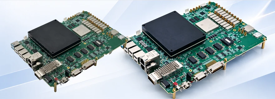
High-Speed RFSoC PCB Manufacturing and Assembly: Key Engineering Considerations
How to get a quote for PCBs Let's run DFM/DFA analysis for...
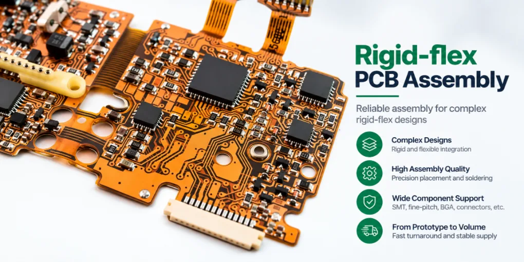
Rigid-flex PCB Assembly for Prototype and Production
Figure 1. Rigid-flex PCB assemblyRigid-flex PCB assembly...

1206 PCB Assembly Services for Prototypes & Production
src="https://hilelectronic.com/wp-content/uploads/2026/08/PC...

Kitted PCBA Services for Customer-Supplied Components
Kitted PCBA is a manufacturing model in which the customer...
How to get a quote for PCBs
Let’s run DFM/DFA analysis for you and get back to you with a report. You can upload your files securely through our website. We require the following information in order to give you a quote:
-
- Gerber, ODB++, or .pcb, spec.
- BOM list if you require assembly
- Quantity
- Turn time
For PCBA services, please provide your BOM (Bill of Materials) and any specific assembly instructions. We also offer DFM/DFA analysis to optimize your designs for manufacturability and assembly, ensuring a smooth production process.