
High Frequency PCB Manufacturer China Selection Guide

Table of Contents
- China’s HF PCB Manufacturing Capability — An Honest Tier Map
- Matching Your Project Type to the Right Manufacturer Tier
- Rogers and Specialty Laminate Supply Chain Realities Inside China
- Equipment and Process Infrastructure That Defines a Genuine HF Manufacturer
- From Trial Order to Qualified Supplier — Building a Working Relationship
- Highleap’s Position in China’s HF PCB Manufacturing Landscape
There are over 2,500 PCB factories in China. Fewer than 5% have processed a Rogers or Taconic laminate in the past 12 months. Of those, perhaps 30–40 factories can hold ±5% impedance on a hybrid Rogers/FR4 stackup with repeatable results across multiple production lots. Selecting the right high frequency PCB manufacturer China demands that you understand this capability distribution — and more importantly, that you can distinguish factories with validated HF process lines from those that list “Rogers compatible” based on a single trial order completed years ago. This guide maps the real capability landscape for engineers and procurement teams sourcing high frequency PCBs from China, and provides the evaluation framework to identify manufacturers that can reliably deliver your specific project requirements.
1. China’s HF PCB Manufacturing Capability — An Honest Tier Map
1.1 Four Capability Tiers
Not every factory that claims high frequency capability has the same depth. A useful way to evaluate China-based manufacturers is by their demonstrated frequency range and material handling competence:
| Tier | Capability | Typical Materials | Frequency Range Served | Estimated Factory Count in China |
|---|---|---|---|---|
| Tier 4 — Standard + low-loss FR4 | Can process Megtron 4/6 and similar low-loss FR4 alternatives | Panasonic Megtron, Isola IS680, Shengyi S1000-2M | Up to ~6 GHz | 200–400 |
| Tier 3 — Rogers hybrid | Processes hybrid stackups (Rogers outer + FR4 inner) with controlled impedance | RO4350B, RO4003C mixed with FR4 | Up to ~15 GHz | 80–150 |
| Tier 2 — Full PTFE processing | Handles all-PTFE stackups with plasma desmear, sodium etch activation, and VLP copper | RT/duroid 5880, RO3003, Taconic TLY | Up to ~40 GHz | 30–50 |
| Tier 1 — mmWave specialist | Validated processes for 77 GHz automotive radar and mmWave phased arrays; VNA-verified insertion loss; HVLP copper; ±3% impedance tolerance | RO3003, Isola Astra MT77, custom PTFE blends | 40–110 GHz | 10–20 |
A 5G base station antenna at 3.5 GHz can be adequately served by a Tier 3 or even Tier 4 factory. A 77 GHz ADAS radar module requires Tier 1 or strong Tier 2 capability. Mismatching your project to the wrong tier is the single most common failure mode when sourcing HF boards from China — the factory accepts the order, struggles with the process, and delivers late with marginal quality.
1.2 How to Verify a Manufacturer’s Actual Tier
Capability matrices and marketing materials do not reveal the tier. These evidence points do:
- Ask for recent impedance test data on the exact material family you need — not a different Rogers grade, not a similar material. If they cannot produce impedance coupon data from the last 90 days on your material, their process is not current.
- Request cross-section images showing etch profile, via plating quality, and lamination bond on PTFE or ceramic-filled substrates. These images are routinely generated by factories with active HF lines; a factory that cannot produce them does not regularly run HF boards.
- Ask about plasma desmear. If the factory desmears PTFE vias with permanganate (the standard FR4 chemistry), they are not a genuine HF manufacturer. PTFE requires plasma treatment (CF₄/O₂) followed by sodium naphthenate activation. This is not optional — it is physics.
- Inquire about copper foil options. A real HF manufacturer stocks or routinely sources RTF, VLP, and HVLP copper foil. If “standard ED copper” is the only option, the factory is not equipped for designs above 6–8 GHz.
2. Matching Your Project Type to the Right Manufacturer Tier
2.1 5G Infrastructure (Sub-6 GHz and mmWave)
Sub-6 GHz 5G base station antenna boards (3.3–4.2 GHz) typically use RO4350B or Megtron 6 in hybrid stackups. These are high-volume applications where panel utilization, consistent impedance across large antenna array panels, and on-time delivery matter more than exotic material capability. A strong Tier 3 manufacturer with material stock and proven volume throughput is the right match.
mmWave 5G boards (24–39 GHz) shift the requirement to Tier 2 minimum — requiring VLP copper, tighter etch control, and VNA-verified insertion loss. The material (often RO3003 or Astra MT77) is less commonly stocked and sourcing lead time becomes a project risk.
2.2 Automotive Radar (77 GHz)
77 GHz ADAS radar is the most demanding mainstream HF PCB application. The board must meet extremely tight Dk uniformity (±0.02 across the panel), use HVLP copper to control conductor loss at 77 GHz, and be manufactured under IATF 16949 quality management. Only Tier 1 factories should be considered. Additionally, automotive programs require PPAP (Production Part Approval Process) documentation — a first article qualification process far more rigorous than standard IPC inspection.
2.3 Satellite Communication (Ka/Ku Band)
Ka-band (26.5–40 GHz) and Ku-band (12–18 GHz) satellite boards often use all-PTFE stackups (RT/duroid 5880, RO3003) with complex multi-layer constructions. Volume is typically low (10–500 units) but reliability requirements are extreme — IPC-6012 Class 3 with full lot traceability. A Tier 2 factory with documented aerospace/defense experience is the minimum. The factory should maintain material traceability from incoming substrate lot numbers through finished board serial numbers.
2.4 IoT, Wi-Fi 6E, and UWB Modules
Wi-Fi 6E (6 GHz), UWB positioning modules, and similar consumer-oriented HF applications are cost-sensitive but still require controlled impedance on low-loss substrates. Hybrid stackups with RO4350B outer layers and FR4 inner cores, or Megtron 6 throughout, are typical. Board sizes are small (often 15×20 mm or less), making panelization efficiency a significant cost factor. A Tier 3 factory with strong small-board panelization practices and fast prototype turnaround is the right fit for design iteration; the same factory can scale to production volumes once the design is frozen.
2.5 RF Test Instruments and Medical Imaging
These applications span wide frequency ranges (DC to 40+ GHz for instruments; 1–15 MHz for ultrasound) and require the manufacturer to handle multiple material types across small, diverse orders. The ideal manufacturer is Tier 2 or above, with experience processing 5+ different substrate families and the engineering flexibility to support non-standard stackup requests. Volume is typically low, so the manufacturer’s willingness to run small lots (5–50 boards) without excessive minimum order markups is a practical consideration.
3. Rogers and Specialty Laminate Supply Chain Realities Inside China
3.1 Material Availability by Grade
Rogers Corporation operates a distribution network in China through authorized regional distributors. Availability varies significantly by grade:
| Material | Dk @ 10 GHz | China Distributor Stock Status | Lead Time if Not Stocked | Practical Advice |
|---|---|---|---|---|
| RO4350B (0.254–1.524 mm, 0.5–1 oz Cu) | 3.48 | Generally stocked in standard configs | 3–7 days | Safest choice for fast turnaround HF boards |
| RO4003C (0.203–1.524 mm) | 3.55 | Stocked in common thicknesses | 5–10 days | Lower Df than RO4350B; good for loss-sensitive designs |
| RT/duroid 5880 (0.254–3.175 mm) | 2.20 | Limited stock; popular thicknesses available | 2–3 weeks | Confirm stock before finalizing design; pre-order for projects |
| RO3003 | 3.00 | Rarely stocked in China | 3–5 weeks (from US) | 77 GHz radar standard material; plan 6+ weeks total |
| Isola Astra MT77 | 3.00 | Very limited in China | 3–6 weeks | Alternative to RO3003 for 77 GHz; similar sourcing challenge |
| Panasonic Megtron 6 | 3.71 | Well-stocked via Asian supply chain | 5–10 days | Cost-effective for sub-10 GHz; processes like FR4 |
3.2 The Manufacturer’s Own Inventory Matters More Than Distributor Stock
A factory that maintains its own substrate inventory — even just the top 3–5 most common Rogers grades and thicknesses — can start production the day your order is placed. A factory that orders material per job adds 5–15 business days to every order. When evaluating a high frequency PCB manufacturer in China, ask specifically: “Which HF substrates do you hold in your own warehouse, and in what thickness/copper configurations?” This is a more useful question than “Which materials can you process?”
3.3 Non-Standard Configurations and MOQ Reality
Rogers laminates in non-standard thickness/copper/foil combinations may have minimum order quantities (MOQ) at the distributor level — sometimes requiring purchase of 20–50 sheets when you only need 2–3 for your prototype. A manufacturer with an existing substrate inventory in standard configurations can avoid this MOQ trap for most projects. For non-standard configurations, a cooperative manufacturer will coordinate with the material distributor to combine your requirement with other customer orders to meet the MOQ threshold.
4. Equipment and Process Infrastructure That Defines a Genuine HF Manufacturer
4.1 Dedicated Lamination with Stored HF Profiles
Rogers, Taconic, and PTFE laminates each require unique lamination temperature, pressure, and dwell time parameters — different from each other and from FR4. A genuine HF manufacturer stores these profiles digitally and loads them per job. Key verification: ask the manufacturer for the lamination profile for your specific material (temperature ramp rate, peak temperature, dwell time, pressure). If they cannot provide this immediately, the profile does not exist in their system.
4.2 Plasma Desmear System
This is the single most reliable indicator of genuine PTFE processing capability. Plasma desmear units (typically using CF₄/O₂ or Ar/O₂ gas mixtures) cost $200,000–$500,000 and occupy dedicated floor space. A factory that claims PTFE capability but uses only wet chemical desmear is not processing PTFE vias correctly. During a factory audit, verify the plasma unit is operational (check maintenance logs, gas cylinder replacement records) — not just installed.
4.3 Impedance Testing Infrastructure
At minimum: a calibrated TDR (time-domain reflectometer) for coupon-based impedance measurement. A serious HF manufacturer also has or has access to a VNA (vector network analyzer) for insertion loss measurement at operating frequency. The VNA frequency range matters — a VNA that measures to 8 GHz cannot validate a 28 GHz design. Ask for the VNA model and frequency range.
4.4 Etch Line Uniformity Control
HF traces require ±0.015 mm trace width uniformity across the panel to maintain impedance tolerance. This requires a well-maintained etch line with consistent spray pressure, nozzle condition monitoring, and etchant temperature control. A factory running HF boards on the same etch line as standard FR4 production (where ±0.025 mm is acceptable) cannot achieve HF-grade trace definition without dedicated attention. The manufacturer should be able to show panel-level trace width measurement data — not spot checks, but systematic measurement across the panel.
4.5 Field Solver for Impedance Modeling
The manufacturer must use a 2D field solver (Polar SI, iCD Stackup Planner, or equivalent) for impedance calculation — not empirical lookup tables or simple online calculators. Field solvers model the actual trapezoidal trace profile, copper roughness correction, and dissimilar dielectric interfaces in hybrid stackups. Without this tool, the manufacturer is guessing at trace widths — which guarantees impedance deviations on HF boards.
5. From Trial Order to Qualified Supplier — Building a Working Relationship
5.1 Phase 1: Qualification Prototype (5–20 boards)
Start with a design that represents your real product requirements — not a simplified test board. Include your actual impedance targets, material, and stackup. The purpose of this phase is to evaluate:
- Engineering responsiveness: How quickly do they complete DFM review? Do they flag real issues or just accept the files?
- Impedance accuracy: Compare their TDR measurement data against your design target. Look at both absolute accuracy and panel-to-panel consistency.
- Documentation quality: Did they provide a complete data package (impedance report, cross-section, material cert, electrical test results)?
- On-time delivery: Did they hit the committed date without expedite surcharges?
5.2 Phase 2: Pre-Production Validation (50–200 boards)
If the prototype passes functional testing, place a pre-production order to stress the process at modest volume. This reveals whether the prototype result was hand-optimized or representative of repeatable production quality. Request:
- Impedance Cpk data across 5+ panels (Cpk ≥ 1.33 for ±5% tolerance).
- Cross-sections from panels at different positions in the production run.
- Any process deviations documented and communicated proactively.
5.3 Phase 3: Production Supplier Status
After successful pre-production, establish the infrastructure for ongoing production:
- Tooling retention: Photo-tools, drill programs, and lamination profiles stored for immediate re-use on repeat orders — no re-engineering each time.
- Substrate consignment: Pre-purchase blank substrates stored at the manufacturer’s facility, eliminating material lead time for future orders.
- Blanket PO: Pre-approved pricing and terms so individual orders require only a release notice — no quote-approve-PO cycle per order.
- Quality agreement: Documented acceptance criteria, test requirements, and corrective action procedures specific to your product.
This phased approach takes 3–6 months but establishes a supplier relationship that delivers consistent quality and compressed lead times for the life of your product.
6. Highleap’s Position in China’s HF PCB Manufacturing Landscape
Highleap Electronics operates as a Tier 2/3 high frequency PCB manufacturer in China, with validated processes for Rogers hybrid and full-PTFE stackups:
- Material inventory: RO4350B, RO4003C, RT/duroid 5880, and Megtron 6 stocked in standard thicknesses — production starts without material sourcing delay. For current inventory details, please contact us to ensure the best material selection for your design.
- Plasma desmear: Operational CF₄/O₂ plasma system for PTFE via processing, with routine cross-section validation.
- Impedance capability: ±5% controlled impedance using Polar SI field solver with production-calibrated Dk/Df inputs; TDR coupon testing on every production panel.
- Copper foil range: Standard ED, RTF, and VLP copper foil available for frequency-specific conductor loss optimization.
- Integrated SMT assembly: Fabrication-to-assembly under one roof with substrate-specific reflow profiles — no inter-facility transit or re-qualification.
- Application experience: 5G antenna arrays, Wi-Fi 6E modules, satellite communication subsystems, and RF front-end modules.
- Volume range: From 5-piece prototype through 10,000+ production lots, with prototype-to-production transition support including first article data packages and SPC establishment.
We support the phased qualification process described in this article with full engineering transparency — including production data sharing, facility access, and detailed documentation at every stage.
Sabrina has over 18 years of experience in the PCB industry, with a strong background in CAM engineering and PCB file review. She supports PCB projects from prototype to volume production, focusing on manufacturability and process reliability. Her work helps engineering teams reduce production risk and achieve stable, high-quality PCB manufacturing results.

Recommended Posts

Wireless Mechanical Keyboard PCB Manufacturing
Table of contentsWireless Keyboard PCB Procurement...

Split Keyboard PCB Manufacturing & Assembly
Table of contentsSplit Keyboard PCBA Procurement...
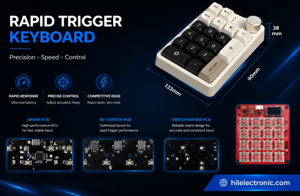
Rapid Trigger Keyboard PCB Manufacturing & PCBA
Table of contentsRapid Trigger PCBA Buying and Performance...
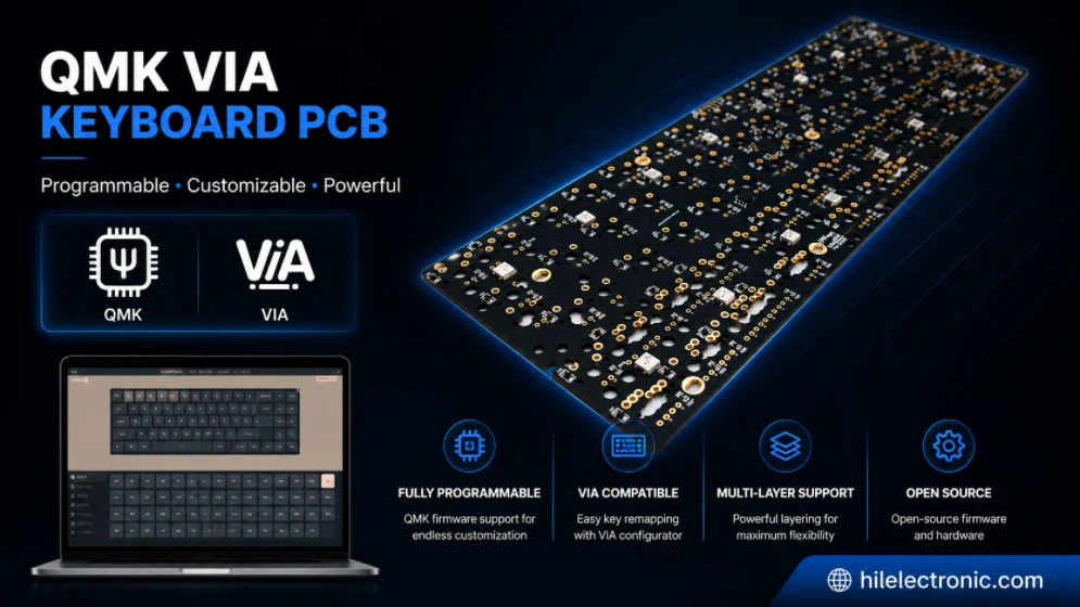
QMK/VIA Keyboard PCB Manufacturing & Assembly
Table of contentsQMK/VIA Keyboard PCB Buying...
How to get a quote for PCBs
Let us run DFM/DFA analysis for you and get back to you with a report.
You can upload your files securely through our website.
We require the following information in order to give you a quote:
-
- Gerber, ODB++, or .pcb, spec.
- BOM list if you require assembly
- Quantity
- Turn time
In addition to PCB manufacturing, we offer a comprehensive range of electronic services, including PCB design, PCBA (Printed Circuit Board Assembly), and turnkey solutions. Whether you need help with prototyping, design verification, component sourcing, or mass production, we provide end-to-end support to ensure your project’s success. For PCBA services, please provide your BOM (Bill of Materials) and any specific assembly instructions. We also offer DFM/DFA analysis to optimize your designs for manufacturability and assembly, ensuring a smooth production process.