
Metal Core PCB vs FR4 PCB: Which Material Fits Your Design?

Introduction: Understanding PCB Material Selection
Choosing the right printed circuit board material is crucial to achieving reliable performance, effective heat dissipation, and cost efficiency. Among the most common options, metal core pcb vs fr4 pcb represents a key design decision that affects both thermal management and manufacturability.
FR4 remains the standard for signal and control circuits in consumer and computing electronics, offering low cost and strong insulation. Metal Core PCBs, on the other hand, provide superior heat conduction for high-power or LED applications where temperature control directly impacts product lifespan. This article compares their material characteristics, highlighting how to balance thermal performance against cost and complexity.
Overview of FR4 PCB Materials
Composition and Structure
FR4 comprises woven fiberglass cloth impregnated with flame-retardant epoxy resin, creating a rigid composite laminate. This combination delivers reliable electrical insulation, dimensional stability, and mechanical strength suitable for most electronic assemblies. The fr4 material exhibits excellent dielectric properties with a dielectric constant typically between 4.2 and 4.8 at 1 MHz. FR4 withstands standard lead-free soldering temperatures up to 260°C without degradation or delamination.
Manufacturing and Cost Advantages
Manufacturing processes for FR4 are highly mature and cost-effective. Drilling, routing, plating, and multilayer lamination proceed with established techniques that minimize production complexity. This accessibility has established FR4 as the default choice for applications ranging from computer motherboards to industrial control systems.
Thermal Performance Limitations
The primary limitation centers on thermal conductivity. FR4 typically conducts heat at approximately 0.3 to 0.4 W/m·K, which proves inadequate when components generate significant thermal loads. In low to moderate power applications where heat dissipation occurs primarily through convection, FR4 performs adequately at minimal cost.

Overview of Metal Core PCB (MCPCB)
Construction and Material Options
Metal Core PCB construction places a thin dielectric insulation layer between copper circuitry and a solid metal base plate. Aluminum serves as the most common substrate material due to its favorable cost-to-performance ratio, though copper cores provide enhanced thermal performance for demanding applications.
This configuration creates a direct thermal pathway from heat-generating components to the metal base, which functions as an integrated heat spreader. The typical MCPCB structure consists of three distinct layers working together.
Thermal Performance Characteristics
Thermal conductivity represents the defining advantage of metal core pcb technology. Aluminum substrates typically achieve 1 to 3 W/m·K, while copper cores can exceed 5 W/m·K. This performance improvement of eight to fifteen times over FR4 enables reliable operation of power electronics and high-brightness LEDs.
The dielectric layer requires careful engineering to maintain electrical isolation while maximizing thermal transfer. Modern thermal dielectric materials achieve this balance through ceramic-filled polymer formulations, with thermal conductivity values ranging from 1 to 3 W/m·K depending on filler concentration.
Primary Application Areas
Metal Core PCB finds primary application in LED lighting systems, automotive power modules, and telecommunications infrastructure where thermal reliability directly affects product longevity. The technology has become standard for high-power applications requiring efficient heat dissipation within compact form factors.

Metal Core PCB vs FR4 PCB: Comparative Analysis
Thermal Management Performance
The primary distinction between metal core pcb and fr4 pcb lies in thermal conductivity. Metal substrates transfer heat far more efficiently, directly influencing component temperature and reliability in power electronics.
-
Shortest thermal path – Direct heat flow from components to the metal base minimizes junction temperatures.
-
Higher thermal conductivity – Aluminum or copper cores achieve 1–3 W/m·K, compared to FR4’s ~0.3 W/m·K.
-
Greater power density – MCPCB supports 5–10 W/in² versus 1–2 W/in² for FR4 without external heat sinks.
As a result, LEDs or power modules on MCPCB operate 15–25 °C cooler, extending service life well beyond FR4-based assemblies.
Electrical Performance Comparison
FR4 remains superior in electrical insulation and signal integrity, enabling multilayer routing and controlled impedance at high frequencies.
-
Stable dielectric constant – Ensures consistent signal propagation up to several gigahertz.
-
High insulation strength – Entire substrate provides voltage isolation for complex circuits.
-
Design flexibility – Supports fine-pitch, multilayer structures without dielectric constraints.
By contrast, MCPCB depends solely on a thin dielectric (50–200 µm) for isolation, limiting circuit density and voltage spacing. For signal-critical applications, FR4 remains the preferred choice unless heat dissipation outweighs electrical performance.
Mechanical Properties and Weight
Both materials maintain rigidity across wide temperature ranges, but their mechanical profiles differ in density and structural function.
-
Higher stiffness – Metal backing prevents warpage during thermal cycling and supports large panels.
-
Dual-function substrate – Metal base acts as both mechanical support and heat spreader.
-
Weight consideration – Aluminum MCPCB (~4.5 kg/m²) is about three times heavier than FR4 (~1.5 kg/m²).
While MCPCB adds mass, it can reduce overall assembly weight by eliminating separate heat sinks or chassis plates.
Manufacturing Complexity
FR4 fabrication benefits from mature, streamlined processes, while MCPCB production demands specialized machining and handling.
-
Standard process flow – FR4 supports high-volume drilling, plating, and finishing with minimal setup.
-
Special tooling – MCPCB requires carbide drills and controlled feed rates for clean edge formation.
-
Extended lead times – MCPCB prototypes typically take 10–15 days versus 5–7 days for FR4 boards.
These additional steps raise manufacturing costs and cycle time but deliver significant thermal and structural benefits in demanding power applications.
Technical Specifications: Metal Core PCB vs FR4 PCB
Property
FR4 PCB
Aluminum MCPCB
Copper MCPCB
Property
FR4 PCB
Aluminum MCPCB
Copper MCPCB
Property
FR4 PCB
Aluminum MCPCB
Copper MCPCB
Property
(1.6mm board)
FR4 PCB
Aluminum MCPCB
Copper MCPCB
Property
FR4 PCB
Aluminum MCPCB
Copper MCPCB
Property
FR4 PCB
Aluminum MCPCB
Copper MCPCB
Property
FR4 PCB
Aluminum MCPCB
Copper MCPCB
Property
FR4 PCB
Aluminum MCPCB
Copper MCPCB
Property
FR4 PCB
Aluminum MCPCB
Copper MCPCB
Design Considerations for Metal Core PCB vs FR4 PCB
Thermal Design Strategy
Effective thermal management is the defining advantage of Metal Core PCB. When evaluating metal core pcb vs fr4 pcb, designers must focus on minimizing thermal resistance between components and the heat-spreading metal base.
-
Shortest thermal path – Direct heat flow from devices to the metal base reduces junction temperature.
-
Thermal via optimization – Proper via placement under power devices improves vertical heat conduction.
-
Copper weight selection – Thicker copper (2–4 oz) enhances lateral spreading before conduction to the base.
-
Component spacing – Controlled layout prevents localized hot spots and cross-heating between parts.
In contrast, FR4 designs depend mainly on copper planes and air convection. Even with dense via arrays, thermal conductivity remains limited by the insulating fiberglass substrate.
Circuit Layout and Layer Stack
FR4 offers extensive layer stacking flexibility for high-density, mixed-signal designs, while MCPCB construction restricts routing to one or two copper layers above the thermal core.
-
Multilayer capability – FR4 supports separate power, signal, and ground planes for complex layouts.
-
Simplified stack structure – MCPCB uses single or double-sided circuits bonded to the metal base.
-
Ground and EMI control – The conductive core doubles as a ground plane and heat spreader.
-
Dielectric optimization – Thinner insulation improves thermal transfer but reduces voltage isolation.
Designers must balance electrical isolation with heat conduction efficiency, coordinating stack-up design between thermal and electrical objectives.
Assembly Process Requirements
Both materials accommodate standard SMT and wave soldering, but MCPCB requires refined thermal profiling due to its high heat capacity.
-
Reflow profile adjustment – Longer preheat and dwell times ensure uniform solder wetting.
-
Consistent peak temperature – Lead-free soldering peaks at 245–260 °C for both substrates.
-
Thermal environment impact – MCPCB lowers component temperatures, supporting higher power ratings.
-
Component reliability – Cooler operation extends semiconductor and capacitor lifespan.
Proper process tuning ensures solder joint integrity and mitigates thermal stress across assemblies using metal-backed substrates.
Cost Analysis: Metal Core PCB vs FR4 PCB
Material and Manufacturing Expenses
The cost difference between metal core pcb and fr4 pcb arises from both materials and fabrication processes.
- FR4 material – Standard 1.6 mm laminates cost around 0.50–1.00 USD per dm².
- Metal Core PCB material – Aluminum MCPCB: 2.00–4.00 USD per dm²; Copper MCPCB: 5.00–8.00 USD per dm².
- Manufacturing impact – Specialized drilling and routing for metal substrates increases production costs by 30–50%.
Performance Value and Lifecycle Economics
Higher upfront costs for MCPCB are often justified by thermal performance and product reliability.
- Extended component life – Lower junction temperatures improve semiconductor and module longevity.
- System efficiency – Higher thermal capacity enables greater power density and potential component consolidation.
- Total cost of ownership – Reduced field failures and warranty claims can offset initial material and processing premiums.

Application Guidelines: When to Choose Each Material
FR4 Optimal Applications
FR4 is ideal for low-heat, signal-focused circuits where cost and manufacturability are priorities.
-
Consumer electronics – Smartphones, tablets, wearables with standard logic boards.
-
Computing peripherals & controllers – Industrial controllers, communication interfaces, and sensor modules.
-
High signal integrity – Supports multilayer layouts and controlled impedance for data paths.
FR4 remains the default choice when thermal demands are minimal and electrical performance is critical.
Metal Core PCB Optimal Applications
Metal Core PCB excels in high-power applications where heat dissipation dictates reliability.
-
LED and lighting – Street lamps, automotive headlights using aluminum MCPCB.
-
Automotive electronics – Power inverters, battery management systems, motor controllers.
-
Telecom & RF – Base station amplifiers and power distribution modules often require copper core MCPCB.
These scenarios justify higher costs due to superior thermal performance and extended operational life.
Hybrid Approach Considerations
Complex systems can combine FR4 and metal core zones to optimize both signal routing and thermal management.
-
Modular layout – High-power components on metal-backed areas; signal traces on FR4.
-
Localized optimization – Matches substrate properties to specific thermal and electrical requirements.
-
Flexible design – Reduces material costs while maintaining performance where needed.
For sophisticated assemblies, the metal core pcb vs fr4 pcb decision can be made per module rather than for the entire board.
Conclusion: Strategic Material Selection for Optimal Performance
Choosing between metal core pcb and fr4 pcb depends on balancing thermal demands, cost, and electrical requirements. FR4 is ideal for signal-critical or low-heat applications, offering mature manufacturing, excellent insulation, and low cost.
Metal Core PCB is necessary when high thermal loads exceed FR4 capabilities, such as in power electronics, high-brightness LEDs, or thermally stressed systems. The higher material and fabrication costs are justified by enhanced heat dissipation, reliability, and extended product life.
No single material fits all applications. Engineers must evaluate heat generation, thermal paths, and component limits to determine the minimum thermal performance needed for reliable operation.
Highleap Electronics Manufacturing Capabilities
At Highleap Electronics, we provide end-to-end PCB solutions tailored to thermal management requirements:
-
Material selection support – Thermal simulation and substrate evaluation to optimize cost and performance.
-
Advanced fabrication – Standard FR4 and Metal Core PCB with aluminum or copper bases, custom stackups, and dielectric options.
-
Thermal management expertise – Experience in LED, automotive, and power electronics applications ensures reliable heat dissipation.
-
Quality assurance – Thermal testing and imaging verify performance before delivery.
-
Turnkey assembly – Complete services from bare board fabrication to component assembly and thermal interface integration.
Contact our engineering team to discuss your thermal challenges and determine whether FR4 or Metal Core PCB best fits your project. We deliver solutions that balance performance, reliability, and manufacturability.

Recommended Posts
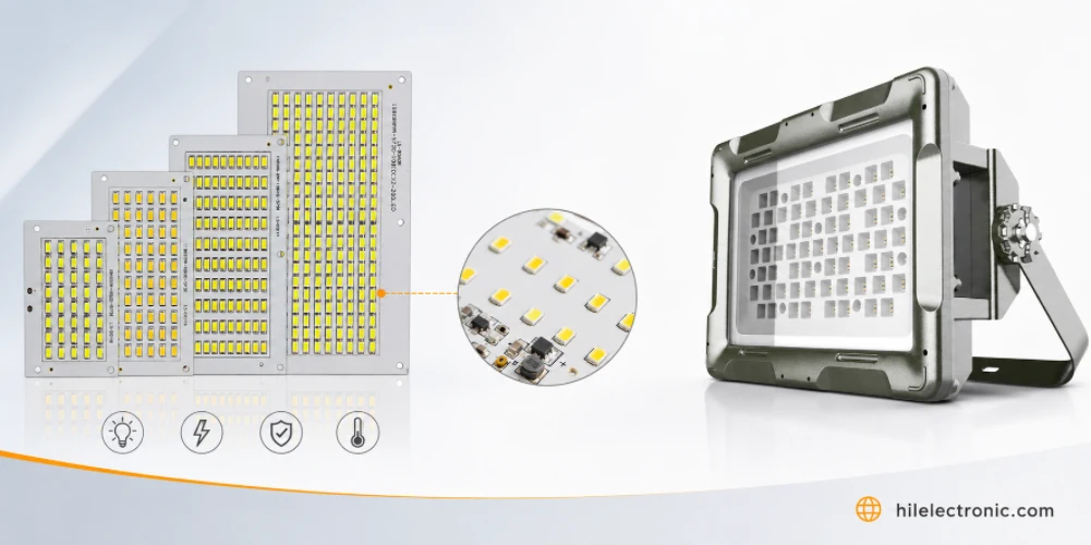
LED Flood Light PCB Manufacturing & Assembly by Highleap Electronics
Figure 1. LED flood light PCB production and assembly...
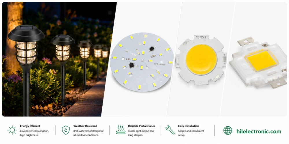
LED Garden Light PCB Manufacturing & Assembly by Highleap Electronics
Figure 1. LED garden light PCB production and assembly...
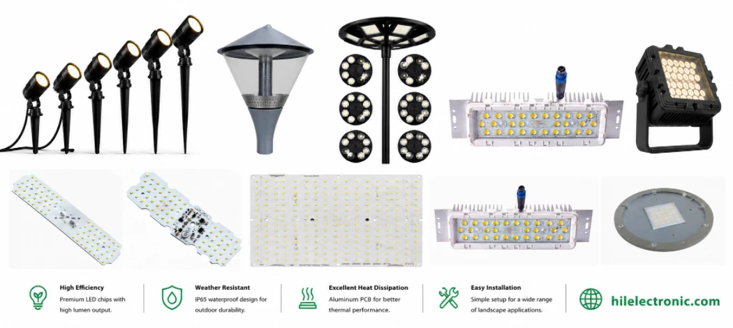
LED Landscape Light PCB Manufacturing — Uplight, Well Light & Underwater Engines
Figure 1. LED landscape light PCB production and assembly...
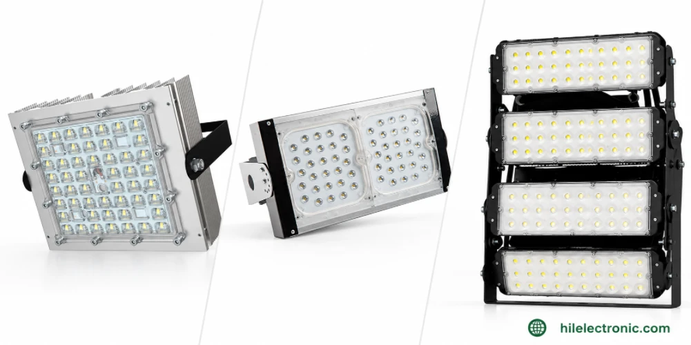
LED Parking Lot Light PCB Manufacturing & Assembly by Highleap Electronics
Figure 1. LED parking lot light PCB production and...
How to get a quote for PCBs
Let‘s run DFM/DFA analysis for you and get back to you with a report. You can upload your files securely through our website. We require the following information in order to give you a quote:
-
- Gerber, ODB++, or .pcb, spec.
- BOM list if you require assembly
- Quantity
- Turn time
In addition to PCB manufacturing, we offer a comprehensive range of electronic services, including PCB design, PCBA, and turnkey solutions. Whether you need help with prototyping, design verification, component sourcing, or mass production, we provide end-to-end support to ensure your project’s success.
For PCBA services, please provide your BOM (Bill of Materials) and any specific assembly instructions. We also offer DFM/DFA analysis to optimize your designs for manufacturability and assembly, ensuring a smooth production process.