
Comparing PTFE and FR4 PCBs for High-Frequency Performance

Introduction
High-frequency circuits operating at GHz-level signals demand substrate materials that deliver low loss, stable impedance, and consistent dielectric properties. When comparing PTFE vs FR4 PCB materials, engineers encounter two fundamentally different solutions. FR4 serves as the industry standard for general-purpose applications, while PTFE-based laminates provide specialized performance for demanding RF and microwave designs. This comparison examines the critical performance differences between these materials to guide your substrate selection for high-frequency projects.
Material Overview: PTFE and FR4 Basics
FR4 Substrate Characteristics
FR4 combines woven fiberglass fabric with epoxy resin, creating a cost-effective substrate with proven reliability across consumer electronics, industrial controls, and computing applications. Its widespread availability and well-established manufacturing processes make it the default choice for circuits operating below 1 GHz. However, FR4’s electrical properties vary with environmental conditions, limiting its effectiveness in precision high-frequency designs.
PTFE (Polytetrafluoroethylene) Substrate Characteristics
PTFE, commonly known by the trademark Teflon, exhibits exceptional electrical stability with a dielectric constant typically between 2.0 and 2.6. Its molecular structure produces extremely low dissipation factors and minimal moisture absorption. PTFE-based laminates maintain consistent performance across temperature variations and deliver the signal integrity required for microwave frequencies, making them essential for RF applications where PTFE vs FR4 PCB performance differences become critical.
Table 1. Material Property Comparison
| Property | FR4 | PTFE |
|---|---|---|
| Dielectric Constant (Dk) | 4.2–4.7 | 2.0–2.6 |
| Dissipation Factor (Df) | 0.015–0.020 | 0.0002–0.001 |
| Thermal Stability | Medium | Excellent |
| Moisture Absorption | Moderate | Very Low |
High-Frequency Electrical Performance Comparison
Signal Loss Characteristics
At frequencies exceeding 1 GHz, the PTFE vs FR4 PCB performance gap widens dramatically. PTFE’s dissipation factor of 0.0002 to 0.001 translates to insertion losses that remain minimal even at 10 GHz, while FR4’s dissipation factor of 0.015 to 0.020 generates losses potentially 10 to 15 times higher. This difference directly impacts system sensitivity, transmission range, and power efficiency in RF circuits.
Impedance Control and Stability
PTFE substrates maintain consistent impedance across temperature and humidity variations due to their hydrophobic nature and stable dielectric properties. FR4’s hygroscopic characteristics cause its dielectric constant to shift with moisture absorption, introducing impedance variations that degrade signal integrity. For precision-controlled 50-ohm transmission lines in demanding applications, PTFE delivers the reliability that FR4 cannot consistently provide.
Phase Stability
Phase consistency becomes critical in phased array antennas, radar systems, and coherent communication links. PTFE’s low and stable dielectric constant ensures minimal phase variation across the operating frequency range. FR4’s higher dielectric constant and temperature-dependent properties introduce phase distortions that compromise system performance, particularly in applications requiring precise timing or beamforming accuracy.

PTFE PCB Manufacturing
Manufacturing and Processing Differences
PTFE PCB Manufacturing Challenges
PTFE processing requires specialized techniques that increase manufacturing complexity. The material’s soft nature complicates drilling, often necessitating entry and exit materials to prevent delamination. Copper adhesion demands specialized bonding processes, and lamination occurs at lower temperatures with higher pressure compared to FR4. Many manufacturers incorporate glass fiber or ceramic fillers to improve dimensional stability and machinability, creating composite materials like PTFE/glass or PTFE/ceramic substrates.
FR4 PCB Manufacturing Advantages
FR4’s mature manufacturing ecosystem provides significant practical benefits. Standard drilling, routing, and lamination equipment handles FR4 efficiently without specialized tooling. The material bonds readily with copper foil and accepts standard soldermask and silkscreen processes. This compatibility with conventional PCB fabrication equipment reduces lead times and expands the pool of qualified manufacturers, making FR4 the pragmatic choice for applications where its electrical limitations remain acceptable.
Alternative RF Materials
Engineers seeking intermediate performance between PTFE vs FR4 PCB extremes can consider hydrocarbon ceramic laminates such as Rogers 4350B or Taconic RF-35. These materials offer improved high-frequency performance over standard FR4 while maintaining compatibility with conventional FR4 processing equipment. This balance makes them attractive for moderate RF applications where pure PTFE performance exceeds requirements or budget constraints.
Cost and Practical Considerations
Material and Manufacturing Cost Comparison
PTFE laminates typically cost three to five times more than FR4, with additional fabrication complexity adding further expense. For prototype quantities or small production runs, this cost differential impacts project budgets significantly. Engineers must evaluate whether the superior electrical performance justifies the investment, considering the specific frequency range, signal loss tolerance, and environmental conditions of their application.
Design Trade-offs
System-level design decisions influence substrate selection. Applications operating below 2 GHz with moderate performance requirements often achieve acceptable results with FR4, particularly when signal paths remain short and loss budgets permit the higher attenuation. For non-critical RF signals or digital circuits within mixed-signal designs, FR4 provides adequate performance at substantially lower cost, allowing designers to allocate budget toward components where advanced materials deliver measurable value.

FR4 PCB Manufacturing
Application Scenarios
PTFE PCB Applications
Microwave communication systems, radar platforms, 5G millimeter-wave modules, and satellite transponders demand PTFE’s exceptional electrical properties. Aerospace and defense applications specify PTFE-based materials for their reliability across extreme temperature ranges and harsh environments. High-power RF amplifiers benefit from PTFE’s thermal stability and low loss, which reduce heat generation and improve efficiency. Any design prioritizing signal integrity above cost considerations typically specifies PTFE or advanced composite laminates.
FR4 PCB Applications
Consumer electronics, computing platforms, automotive control systems, and industrial equipment rely on FR4’s proven reliability and cost-effectiveness. Digital circuits, power management sections, and lower-frequency analog designs perform adequately on FR4 substrates. The material’s widespread acceptance, established supply chains, and comprehensive design resources make it the logical choice for commercial products where high-frequency performance requirements remain modest.
Hybrid Stackup Designs
Mixed-layer constructions combine PTFE vs FR4 PCB materials within a single board assembly, placing PTFE layers where high-frequency signals propagate while using FR4 for power distribution and lower-speed digital circuits. This hybrid approach optimizes both performance and cost, concentrating expensive materials where they provide maximum benefit. The technique requires careful impedance planning and thermal management but delivers practical solutions for complex mixed-signal systems.
How to Choose Between PTFE and FR4 for Your Project
Selection Criteria
Operating frequency serves as the primary selection criterion. Applications below 1 GHz generally perform satisfactorily with FR4, while designs exceeding 5 GHz typically require PTFE or advanced composites. Insertion loss tolerance, environmental operating conditions, and budget constraints further refine the selection. For projects where signal integrity directly impacts system performance or regulatory compliance, PTFE’s superior characteristics justify the additional investment. Conversely, cost-sensitive applications with relaxed RF requirements benefit from FR4’s economic advantages.
Decision Framework
Evaluate your design frequency, calculate acceptable insertion loss based on link budget analysis, and assess environmental exposure including temperature extremes and humidity. Consider production volumes, as higher quantities reduce PTFE’s per-unit cost impact. Prototype testing with both materials can validate performance assumptions and identify potential issues before committing to volume production. Consulting with your PCB fabricator early in the design phase ensures material selection aligns with their capabilities and your schedule requirements.
Table 2. PTFE vs FR4 PCB Comprehensive Comparison
| Comparison Factor | FR4 | PTFE |
|---|---|---|
| Dielectric Constant (Dk) | 4.2–4.7 | 2.0–2.6 |
| Dissipation Factor (Df) | 0.015–0.020 | 0.0002–0.001 |
| Signal Loss at High Frequency | Higher (significant above 1GHz) | Minimal (excellent at 10GHz+) |
| Impedance Stability | Affected by temperature and humidity | Highly stable across conditions |
| Phase Stability | Moderate | Excellent |
| Thermal Stability | Medium (-50°C to 130°C) | Excellent (-200°C to 260°C) |
| Moisture Absorption | Moderate (0.1-0.15%) | Very low (<0.01%) |
| Drilling & Processing | Easy, standard processes | Difficult, requires special techniques |
| Copper Adhesion | Excellent | Poor (requires surface treatment) |
| Manufacturing Maturity | Highly mature, widely available | Specialized processes required |
| Relative Cost | Baseline (1x) | 3–5x higher |
| Lead Time | Short | Longer |
| Typical Frequency Range | DC to 1GHz | 1GHz to 100GHz+ |
| Primary Applications | Consumer electronics, computers, automotive | Microwave, radar, 5G RF, satellite |
| Design Complexity | Standard | Requires RF expertise |
| Best Use Case | Cost-sensitive, general purpose | Performance-critical high-frequency |
Conclusion
The PTFE vs FR4 PCB comparison reveals fundamental trade-offs between electrical performance and practical considerations. PTFE’s low dielectric constant, minimal loss tangent, and exceptional stability make it indispensable for high-frequency applications where signal integrity cannot be compromised. However, its higher cost and manufacturing complexity require justification through genuine performance requirements. FR4 remains the industry workhorse for applications where its electrical limitations fall within acceptable bounds, offering proven reliability and economic efficiency.
Understanding these materials’ characteristics enables informed substrate selection that balances technical requirements with project constraints. For applications demanding maximum high-frequency performance, PTFE delivers the capabilities modern RF systems require.

Recommended Posts
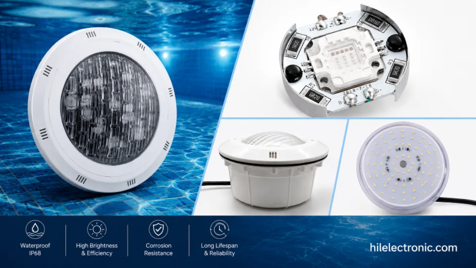
Underwater & Pool LED Light PCBs: IP68 Potted Boards, Low-Voltage Drivers & Safety
Figure 1. LED pool light PCB manufacturing reference....
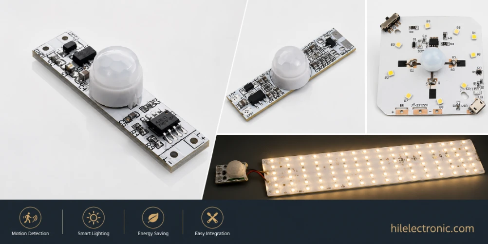
Motion Sensor & Smart LED Light PCBs: Sensor, Control, Driver & Wireless Boards
Figure 1. motion sensor LED light PCB manufacturing...
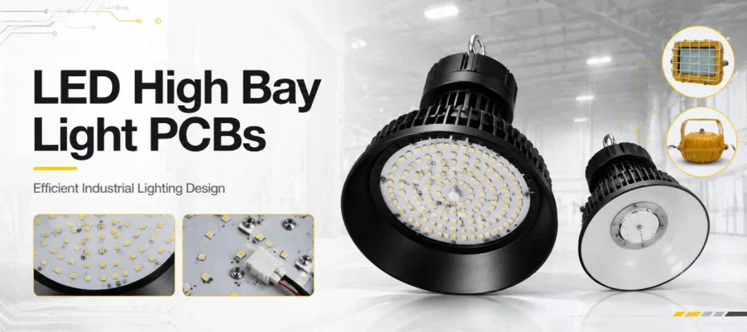
LED High Bay Light PCBs: Metal-Core Light Engines, Drivers & Turnkey Boards Built to Spec
Figure 1. LED high bay light PCB manufacturing reference....
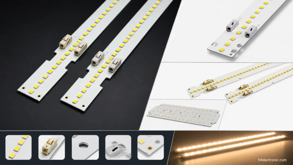
LED Linear & Strip Light PCBs: Long-Format Engines, Flexible & Rigid-Flex Boards
Figure 1. LED linear light PCB manufacturing reference....
How to get a quote for PCBs
Let‘s run DFM/DFA analysis for you and get back to you with a report. You can upload your files securely through our website. We require the following information in order to give you a quote:
-
- Gerber, ODB++, or .pcb, spec.
- BOM list if you require assembly
- Quantity
- Turn time
In addition to PCB manufacturing, we offer a comprehensive range of electronic services, including PCB design, PCBA, and turnkey solutions. Whether you need help with prototyping, design verification, component sourcing, or mass production, we provide end-to-end support to ensure your project’s success.
For PCBA services, please provide your BOM (Bill of Materials) and any specific assembly instructions. We also offer DFM/DFA analysis to optimize your designs for manufacturability and assembly, ensuring a smooth production process.