
Low PIM PCB Design: Engineering Clean Signal Paths in High-Frequency Systems

Introduction
As wireless systems push toward higher frequencies and tighter linearity requirements, low PIM PCB design becomes critical to maintaining clean signal paths and minimizing unwanted distortion. Passive Intermodulation (PIM) represents interference generated when RF signals interact with nonlinear elements in passive components, causing spurious emissions that degrade system performance.
In modern 5G infrastructure, satellite communications, and radar applications operating at multi-gigahertz frequencies, even minute nonlinearities produce measurable interference. Low PIM PCB design addresses this challenge through systematic material selection, surface treatment optimization, and controlled manufacturing processes.
In cellular base stations where transmit and receive bands operate simultaneously, third-order intermodulation products can fall directly into sensitive receive channels, reducing system sensitivity by 10 dB or more. Proper low PIM PCB design ensures signal integrity remains uncompromised across the entire RF chain.
Understanding Passive Intermodulation (PIM)
PIM Formation Mechanisms
Passive Intermodulation occurs when two or more RF signals mix through nonlinear junctions in nominally passive structures, creating spurious frequency components at integer combinations of input frequencies. When carriers at f₁ and f₂ traverse a nonlinear interface, they generate products at 2f₁–f₂, 2f₂–f₁, and higher-order combinations. Unlike active intermodulation in amplifiers, PIM arises from metal-to-metal contacts, oxidized surfaces, ferromagnetic contaminants, and microscopic surface irregularities exhibiting current-dependent conductivity.
Active Versus Passive Intermodulation
Active intermodulation originates in semiconductor junctions where intentional signal processing occurs, following predictable transfer functions. Passive intermodulation manifests in supposedly linear structures through contact nonlinearity, electrochemical effects at dissimilar metal interfaces, and current-induced heating that modulates conductivity. PIM proves particularly problematic because it appears unpredictably, varies with environmental conditions, and can arise from manufacturing defects invisible to standard electrical testing.
Frequency Sensitivity in PCB Structures
PIM severity increases at gigahertz frequencies where skin effect concentrates current at surface boundaries, amplifying the impact of surface roughness and oxide layers. At 2 GHz and above, submicron surface variations become electrically significant, making PCB surface quality paramount for low PIM PCB performance. Temperature cycling exacerbates these effects as differential thermal expansion creates microscopic movement at interfaces, modulating contact resistance.
Root Causes of PIM in Low PIM PCB Design
Material-Related Contributors
Copper surface roughness directly influences PIM generation through current crowding at microscopic peaks and valleys. Rolled copper with rough profiles exhibits higher PIM than electrodeposited copper with controlled surface topology. Dielectric materials containing residual monomers or moisture introduce bulk nonlinearity, while lossy substrates generate heat that modulates local conductivity under high-power RF excitation.
Design-Related Sources
Critical design factors affecting low PIM PCB performance include:
- Current distribution – Nonuniform paths force signal energy through restricted areas where current density approaches material limits
- Ground plane integrity – Discontinuous planes create return current loops that concentrate fields at PCB edges
- Via structures – Barrel plating quality determines PIM performance, particularly in high-layer-count stackups
- Interface quantity – Each additional junction introduces potential nonlinear contact points
Manufacturing and Assembly Factors
Solder flux residues form insulating barriers at critical junctions, forcing current through microscopic contact points that exhibit nonlinear behavior. Mechanical stress from connector mounting creates pressure gradients producing inconsistent metal-to-metal contact. Contamination during fabrication introduces foreign materials with magnetic properties or electrochemical potential differences that generate PIM under RF excitation.
Environmental Influences
Thermal cycling drives interface oxidation and creates differential expansion between dissimilar materials, modulating contact resistance over operational temperature ranges. Humidity ingress promotes electrochemical corrosion at exposed copper surfaces and plated interfaces. These time-dependent mechanisms mean PIM performance degrades over product lifetime, making initial design margins essential.

Antennas
Low PIM PCB Design Techniques and Best Practices
Strategic Material Selection
Low PIM PCB design begins with substrate selection prioritizing materials exhibiting minimal dielectric nonlinearity and low dissipation factors. Rogers RO4350B and PTFE-based laminates demonstrate superior PIM performance through stable permittivity and minimal moisture absorption. Copper foil selection emphasizes smooth profiles achieved through electrodeposition, with reverse-treated foils offering reduced surface roughness. Avoiding ferromagnetic materials proves essential, as they introduce hysteretic nonlinearity even at modest power levels.
Optimized Surface Finishes
Surface finish selection significantly impacts low PIM PCB performance:
- ENIG (Electroless Nickel Immersion Gold) – Higher PIM due to nickel’s ferromagnetic properties
- EPIG (Electroless Palladium Immersion Gold) – Eliminates magnetic materials while providing oxidation resistance
- Immersion Silver – Excellent conductivity but requires careful handling to prevent tarnishing
- OSP (Organic Solderability Preservative) – Minimizes interface complexity but provides limited shelf life
Controlled Stackup and Layout
Symmetrical layer stackups with continuous ground planes minimize current path variation and reduce field concentration points. Signal routing maintains controlled impedance throughout transitions, avoiding sudden width changes or reference plane gaps that concentrate current density. Via design emphasizes filled and plated structures eliminating air gaps where oxidation could occur. low PIM PCB layouts minimize total interface count by reducing unnecessary vias and consolidating critical RF paths on single layers.
Precision Connector Integration
Connector selection focuses on mechanically robust designs with controlled contact pressure distribution. DIN 7/16 and low-PIM N-type connectors feature silver-plated beryllium copper contacts with spring-loaded engagement maintaining consistent interface conductivity across temperature and vibration. Transition design eliminates sharp bends and ensures smooth field evolution from coaxial to planar geometries.
Manufacturing Process Control
Assembly procedures for low PIM PCB production include:
- Surface preparation – Solvent cleaning and ionized air treatment before final enclosure
- Solder paste selection – Non-aggressive flux formulations that minimize residues
- Reflow profiling – Controlled thermal stress while ensuring complete solder wetting
- Post-assembly inspection – Optical examination of critical RF junctions and selective conformal coating
Testing and Validation of Low PIM PCB Performance
PIM Testing Methodology
Standard PIM testing employs two high-power carriers separated by channel bandwidth, typically at 2×20W (43 dBm), while measuring third-order intermodulation products at 2f₁–f₂ and 2f₂–f₁ frequencies. Test systems require exceptional isolation exceeding 160 dB between transmit and receive paths to distinguish actual PIM from measurement artifacts. Low PIM PCB modules undergo testing in shielded chambers using calibrated combiners and low-PIM loads.
Frequency and Power Ranges
Cellular infrastructure testing typically spans 700 MHz to 6 GHz with transmit powers from 20W to 80W per carrier, representing operational conditions in macro base stations. Satellite applications extend testing to Ku-band and Ka-band frequencies where spacecraft power amplifiers generate significant RF power. The relationship between input power and PIM products follows third-order or fifth-order power law behavior, allowing extrapolation from test conditions to operational scenarios.
PCB-Level Validation Methods
Dedicated test fixtures enable low PIM PCB characterization during development, identifying problematic areas before system integration. These fixtures employ precision connectors and controlled launch structures to isolate PCB contributions from test equipment. Thermal chambers subject boards to temperature cycling while monitoring PIM variation, revealing temperature-dependent mechanisms. Microanalysis techniques including scanning electron microscopy identify contaminants or structural anomalies at critical interfaces.
Quality Control Implementation
Production testing establishes PIM specifications appropriate to application requirements, typically ranging from –110 dBc to –160 dBc depending on system sensitivity. Statistical process control monitors PIM performance across manufacturing lots, detecting process drift before yield impacts occur. Surface inspection protocols verify cleanliness and finish integrity at solder joints and connector interfaces.
Practical Applications and Performance Impact
Critical Application Domains
Fifth-generation cellular infrastructure depends on low PIM PCB design to support massive MIMO antenna arrays where hundreds of RF channels operate simultaneously. Satellite communication systems require PIM levels below –150 dBc to prevent interference with sensitive uplink receivers processing signals near noise floor. Phased array radar applications combine high peak power with wideband operation, making PIM mitigation essential for detecting weak targets.
Performance Impact Analysis
Field deployments demonstrate that reducing PIM from –125 dBc to –150 dBc improves base station receiver sensitivity by 3 to 5 dB, directly translating to extended coverage radius or improved building penetration. In satellite ground stations, superior low PIM PCB performance enables operation with smaller antennas or reduced transmit power while maintaining link margins. Radar systems benefit from improved clutter rejection and target discrimination when spurious responses no longer mask genuine returns.
Design Integration Strategies
Successful low PIM implementations extend beyond individual PCB design to encompass complete RF module architecture. Antenna feed networks benefit from integrated bias tees and filtering implemented with low-PIM transmission line structures. System-level analysis identifies cumulative PIM contributions from multiple assemblies, allocating budgets to individual modules based on their position in the signal chain and operational power levels.
Conclusion
Low PIM PCB design represents a systematic engineering discipline combining materials science, electromagnetic theory, and precision manufacturing to eliminate nonlinear interference sources in high-frequency systems. As wireless infrastructure evolves toward higher frequencies, wider bandwidths, and increased channel density, PIM mitigation becomes increasingly critical. Successful implementation requires attention to every aspect of PCB realization, from initial material selection through final assembly processes.
Highleap Electronics delivers comprehensive low PIM PCB solutions through:
- Advanced material selection – Low-loss laminates including Rogers and PTFE substrates with controlled copper surface profiles
- Optimized surface finishes – Nickel-free plating options (EPIG, immersion silver) that eliminate ferromagnetic interfaces
- Precision manufacturing – Controlled plating processes, contamination-free assembly environments, and torque-specified connector installation
- Rigorous testing protocols – PIM validation across operational frequency ranges with temperature cycling and statistical process control
- Engineering collaboration – Design support for stackup optimization, material specification, and performance validation
Contact our engineering team to discuss your low PIM PCB requirements and learn how our proven manufacturing processes can support your next-generation RF system development.

Recommended Posts

LED Garden Light PCB Manufacturing & Assembly by Highleap Electronics
Figure 1. LED garden light PCB production and assembly...

LED Landscape Light PCB Manufacturing — Uplight, Well Light & Underwater Engines
Figure 1. LED landscape light PCB production and assembly...

LED Parking Lot Light PCB Manufacturing & Assembly by Highleap Electronics
Figure 1. LED parking lot light PCB production and...
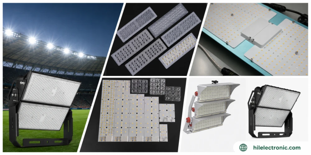
LED Stadium Light PCB Manufacturing — Very-High-Power Engines & Flicker-Free Drivers
Figure 1. LED stadium light PCB production and assembly...
How to get a quote for PCBs
Let‘s run DFM/DFA analysis for you and get back to you with a report. You can upload your files securely through our website. We require the following information in order to give you a quote:
-
- Gerber, ODB++, or .pcb, spec.
- BOM list if you require assembly
- Quantity
- Turn time
In addition to PCB manufacturing, we offer a comprehensive range of electronic services, including PCB design, PCBA, and turnkey solutions. Whether you need help with prototyping, design verification, component sourcing, or mass production, we provide end-to-end support to ensure your project’s success.
For PCBA services, please provide your BOM (Bill of Materials) and any specific assembly instructions. We also offer DFM/DFA analysis to optimize your designs for manufacturability and assembly, ensuring a smooth production process.