
What Is a Zero PCB? A Beginner-Friendly Guide to DIY Prototyping Boards

Figure 1. Zero PCB Board
Introduction
A zero PCB is a general-purpose prototyping board featuring a grid of pre-drilled holes without any predefined copper traces. Unlike manufactured printed circuit boards with fixed routing, a zero PCB allows engineers and hobbyists to design custom circuits by manually connecting components through soldering.
Why Zero PCBs Are Popular in Prototyping
Zero PCBs serve as essential tools for electronics learning and rapid prototyping. They bridge the gap between breadboard testing and professional PCB manufacturing, offering a permanent yet flexible solution for circuit development. Students, engineers, and makers rely on these boards to validate designs before committing to custom fabrication.
Zero PCB vs Standard Manufactured PCB
Standard PCBs feature factory-etched copper traces, solder masks, and silkscreen markings designed for specific circuits. Zero PCBs, in contrast, provide blank canvases where users define all connections. This distinction makes zero PCBs ideal for one-off prototypes while manufactured boards excel in production environments.
What You Will Learn
This guide covers zero PCB fundamentals, working principles, board types, practical applications, advantages, limitations, and guidance on choosing between zero PCB prototyping and custom PCB manufacturing for your projects.
What Is a Zero PCB?
Definition and Terminology
A zero PCB—also called a general-purpose PCB, perfboard, or dot-matrix PCB—is a prototyping board with evenly spaced holes surrounded by copper pads. Each pad remains electrically isolated, giving users complete freedom to create any circuit topology through manual wiring and soldering.
Origin of the Name “Zero PCB”
The term “zero” refers to the absence of manufacturer-defined circuitry. With zero pre-routed traces and zero preset connections, these boards arrive as blank substrates. Users build circuits from scratch, hence the “zero” designation indicating no factory customization.
Key Characteristics
Zero PCBs share several defining features:
- No predefined copper traces between pads;
- A uniform grid of through-holes for component mounting;
- Complete user control over circuit routing.
These characteristics distinguish them from application-specific boards with fixed layouts.
Common Materials
Manufacturers produce zero PCBs using various substrates. FR-4 fiberglass offers durability and heat resistance for demanding applications. FR-2 phenolic and paper-based materials provide economical options for simple circuits. Material selection depends on thermal requirements, mechanical stress, and budget constraints.
How Does a Zero PCB Work?
Hole Matrix and Spacing
Standard zero PCBs use 2.54 mm (0.1 inch) hole spacing, matching the pin pitch of most through-hole components including DIP integrated circuits, resistors, and capacitors. This universal spacing ensures compatibility with common electronic parts and simplifies component placement.
Component Mounting
Components insert through holes from the top side, with leads protruding on the copper-pad side. After positioning, soldering secures components mechanically and creates electrical connections to the pads. This through-hole mounting method accommodates most discrete components and many integrated circuits.
Wiring Methods
Circuit routing on zero PCBs employs several techniques. Solder bridges connect adjacent pads directly. Jumper wires link distant points using insulated hookup wire. Bare copper wire soldered along pad rows creates bus connections. Each method suits different circuit densities and complexity levels.
Design Flexibility
The absence of fixed traces enables real-time circuit modifications during assembly. Engineers can adjust layouts, add components, or reroute connections without ordering new boards. This adaptability makes zero PCBs invaluable for iterative development and experimental circuits.
Types of Zero PCBs
Single-Sided Zero PCB
Single-sided zero PCBs feature copper pads on one surface only. These boards suit simple circuits with minimal crossing connections. Their lower cost and straightforward assembly make them popular choices for basic DIY electronics projects and educational applications.
Double-Sided Zero PCB
Double-sided variants provide copper pads on both surfaces, significantly expanding routing options. Through-hole plating may connect top and bottom layers. These boards accommodate more complex circuits where single-sided routing proves insufficient or creates excessive wire crossings.
Stripboard (Veroboard)
Stripboards feature continuous copper strips running in parallel rows rather than isolated pads. This configuration simplifies bus connections and suits circuits with common rails. Users cut strips where isolation is needed. The structured layout benefits organized prototyping with clear signal paths.
Matrix Perforated Board
Matrix perforated boards maintain isolated pads at every hole position, offering maximum design freedom. No predefined connections exist between any points. This type requires more manual wiring but accommodates virtually any circuit topology without trace-cutting modifications.
Breadboard vs Zero PCB
Breadboards allow solderless, reusable connections ideal for temporary testing. Zero PCBs create permanent soldered assemblies for finished prototypes. Choose breadboards for rapid experimentation and zero PCBs when circuits require durability, reliability, or deployment outside the lab.

Figure 2. Zero PCB and Breadboard
Common Applications of Zero PCBs
Educational Electronics Projects
Zero PCBs provide hands-on learning platforms for students studying electronics fundamentals. Building circuits manually reinforces theoretical concepts, develops soldering skills, and teaches troubleshooting techniques that automated PCB assembly cannot replicate.
Low-Volume Prototype Circuits
Engineers use zero PCBs to construct working prototypes before investing in custom PCB fabrication. These boards validate circuit functionality, identify design flaws, and enable rapid iterations without the lead time and expense of manufactured boards.
Testing Analog and Digital Circuits
Simple analog circuits like amplifiers and filters, along with basic digital logic, prototype efficiently on zero PCBs. Test circuits for sensor interfaces, signal conditioning, and microcontroller peripherals commonly use these boards during development phases.
Repairs, Modifications, and IoT Experiments
Zero PCBs serve repair applications where replacement circuits are unavailable. They also support module modifications and small-scale IoT experiments. Hobby builders frequently choose these boards for custom sensor nodes, controllers, and one-off electronic devices.
Advantages of Zero PCBs
Complete Layout Flexibility
Zero PCBs impose no constraints on circuit topology. Users design any layout that fits the available space. This freedom supports unconventional designs, last-minute changes, and creative solutions impossible with fixed-trace boards.
Low Cost and Wide Availability
Zero PCBs cost significantly less than custom-manufactured boards, especially for single units. Electronics suppliers worldwide stock various sizes and types. This accessibility makes prototyping affordable for hobbyists, students, and budget-conscious development projects.
Rapid Prototyping Without Design Software
Building on zero PCBs requires no CAD software, Gerber file generation, or manufacturing coordination. Engineers can move directly from schematic to physical circuit, reducing development time dramatically for proof-of-concept work and experimental builds.
Ideal for Learning and Experimentation
The manual construction process develops essential skills including component identification, soldering technique, and systematic troubleshooting. These educational benefits make zero PCBs preferred platforms for electronics courses and self-directed learning.

Limitations of Zero PCBs
Unsuitable for High-Density or High-Speed Designs
Zero PCBs cannot accommodate surface-mount components with fine-pitch leads or ball-grid arrays. High-speed digital circuits suffer from uncontrolled impedances and excessive parasitic capacitance inherent in manual wiring approaches.
Manual Routing Increases Error Risk
Hand-wired connections introduce opportunities for mistakes: incorrect routing, cold solder joints, and accidental bridges between traces. Complex circuits require careful attention and thorough inspection to achieve reliable operation.
No Solder Mask, Silkscreen, or Controlled Impedance
Professional PCB features like protective solder masks, component labeling silkscreens, and impedance-controlled traces are absent from zero PCBs. These limitations affect assembly ease, documentation, and suitability for sensitive RF or high-frequency applications.
Reliability and Thermal Constraints
Circuit reliability depends entirely on assembly quality and operator skill. Thermal performance suffers from limited copper area and poor heat spreading. High-current applications may require supplementary heat management beyond what zero PCBs can provide.
Practical Tips for Using Zero PCBs
Plan Before Soldering
Sketch component placement and routing paths before heating your soldering iron. Planning prevents crowded layouts, minimizes wire crossings, and identifies potential issues early. Even simple circuits benefit from deliberate organization.
Minimize Wire Lengths and Use Color Coding
Keep signal wires short to reduce noise pickup and parasitic inductance. Use color-coded jumper wires consistently—red for power, black for ground, and distinct colors for different signals. This practice simplifies troubleshooting and documentation.
Secure Components and Inspect Joints
Apply adhesive to stabilize heavy components before soldering. Inspect every solder joint for bridges, cold connections, and insufficient wetting. Methodical verification catches problems before power-up and prevents damage from short circuits.
Start Simple
Beginners should start with single-sided matrix boards and low-complexity circuits. Build confidence through successful projects before attempting dense layouts or critical applications. Experience develops the skills needed for more challenging zero PCB assemblies.
Conclusion
Zero PCBs provide engineers with a flexible and practical platform for building and evaluating circuits in the early development stages. With a blank layout and full freedom in routing, they allow quick assembly, modification, and validation of design ideas without additional fabrication steps. By understanding the capabilities and limitations of this type of board, engineers can prototype more efficiently and move through each design iteration with greater confidence.

Recommended Posts
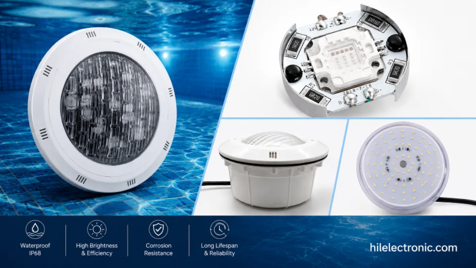
Underwater & Pool LED Light PCBs: IP68 Potted Boards, Low-Voltage Drivers & Safety
Figure 1. LED pool light PCB manufacturing reference....
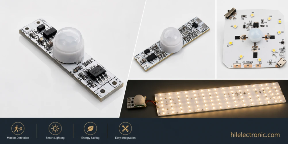
Motion Sensor & Smart LED Light PCBs: Sensor, Control, Driver & Wireless Boards
Figure 1. motion sensor LED light PCB manufacturing...

LED High Bay Light PCBs: Metal-Core Light Engines, Drivers & Turnkey Boards Built to Spec
Figure 1. LED high bay light PCB manufacturing reference....
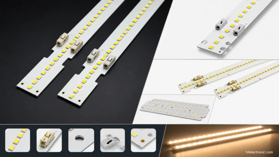
LED Linear & Strip Light PCBs: Long-Format Engines, Flexible & Rigid-Flex Boards
Figure 1. LED linear light PCB manufacturing reference....
How to get a quote for PCBs
Let‘s run DFM/DFA analysis for you and get back to you with a report. You can upload your files securely through our website. We require the following information in order to give you a quote:
-
- Gerber, ODB++, or .pcb, spec.
- BOM list if you require assembly
- Quantity
- Turn time
In addition to PCB manufacturing, we offer a comprehensive range of electronic services, including PCB design, PCBA, and turnkey solutions. Whether you need help with prototyping, design verification, component sourcing, or mass production, we provide end-to-end support to ensure your project’s success.
For PCBA services, please provide your BOM (Bill of Materials) and any specific assembly instructions. We also offer DFM/DFA analysis to optimize your designs for manufacturability and assembly, ensuring a smooth production process.