
High Reliability PCB Assembly: Process Control and Traceability
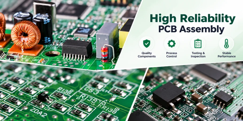
Highleap Electronics manufactures high reliability PCB assemblies for products where a field failure has consequences beyond a warranty return: medical devices, automotive electronics, industrial control and power systems, aerospace and defense equipment, and infrastructure that must run unattended for years. We fabricate the bare boards and assemble them to the workmanship class, materials and verification steps defined in your requirements.
High reliability is not a label applied at the end of the line. It is set by three decisions made before the build: the acceptance criteria the boards are built and inspected to, the materials and processes that determine how solder joints and laminates age, and the evidence the manufacturer must provide that each lot meets the requirement. This page explains how those decisions translate into a PCBA specification, which processes and tests matter, and what to verify when qualifying a manufacturer.
Table of contents
- Defining High Reliability Requirements for a PCBA
- IPC Class 3 Assembly: What Changes on the Line
- Bare Board and Material Choices That Affect Reliability
- Process Controls for Reliable Solder Joints
- Inspection, Test and Board Protection
- Traceability and Change Control
- Qualifying a High Reliability PCBA Manufacturer
- High Reliability PCB Assembly FAQ
HIGH RELIABILITY PCB ASSEMBLY
Building to Class 3 or an Industry Standard?
Send design files with your workmanship class, test requirements and documentation needs. We review the requirements before quoting.
Request a High Reliability Quote →Defining High Reliability Requirements for a PCBA
“High reliability” means different things in different industries. A purchase order that only says “high reliability” leaves the manufacturer to guess, and two suppliers will quote two different products. A useful requirement states the following:
| Requirement | What to specify | Why it matters |
|---|---|---|
| Bare board acceptance | IPC-6012 class, plus any customer-specific requirements | Sets plating thickness, annular ring and allowable defects in the laminate |
| Assembly workmanship | IPC-A-610 class (and J-STD-001 if your industry requires it) | Sets solder fill, wetting and component placement acceptance |
| Operating environment | Temperature range, thermal cycling, humidity, vibration, contamination | Drives laminate selection, component grades, coating and mechanical support |
| Verification | Required inspections, electrical and functional tests, any stress screening | Defines what evidence each lot ships with |
| Records | Traceability level, retention period, certificates of conformance | Determines whether a field failure can be traced to a lot and root cause |
Industry quality systems add their own expectations: ISO 13485 for medical devices, IATF 16949 for automotive supply chains, and aerospace and defense customer requirements. Highleap’s quality system certifications are listed on our certifications page; state the standard your product falls under in the RFQ so the build documentation is set up from the first lot.
IPC Class 3 Assembly: What Changes on the Line
Most high reliability programs specify IPC Class 3. The difference from Class 2 is not a different machine, it is a narrower acceptance window and more inspection effort, which is why Class 3 boards cost more.
- Plated through-hole fill: Class 3 requires a higher minimum vertical solder fill in through-holes than Class 2. Thick boards and connections to large copper planes need through-hole processes and thermal design that reach it.
- Component placement: allowable side overhang and end-joint offset are smaller, so placement accuracy and pad design must leave less margin for error.
- Wetting and joint profile: conditions accepted as process indicators in Class 2 can be defects in Class 3.
- Bare board: IPC-6012 Class 3 requires thicker hole-wall copper and larger annular rings, which affect drill and pad design.
Class 3 should be specified in the design phase, not added at the order stage. A layout designed to Class 2 pad and annular ring rules may not be manufacturable to Class 3 without changes. Our comparison of IPC Class 2 vs Class 3 PCB assembly covers the acceptance differences in detail.
Does Every Board in a High Reliability Product Need Class 3?
Not always. Specifying Class 3 only where the function requires it, for example a control board but not a display interface board, can control cost. The decision should be made by the product’s engineering team based on the consequence of failure and the applicable industry standard.
Bare Board and Material Choices That Affect Reliability
Many long-term field failures start in the bare board rather than in the solder joints. Thermal cycling stresses plated through-holes along the Z axis; repeated reflow and rework stress the laminate; conductive anodic filament growth can occur between closely spaced holes in humid environments.
- Laminate Tg and decomposition temperature: lead-free reflow, double-sided assembly and rework require laminates rated for multiple thermal excursions.
- Z-axis expansion: lower Z-axis CTE reduces stress on plated barrels during thermal cycling, which matters for thick, high-layer-count boards.
- Via structure: stacked microvias, filled vias and via-in-pad need process qualification; staggered microvias are often preferred where reliability margin is critical.
- Surface finish: ENIG, ENEPIG, immersion silver and OSP differ in shelf life, flatness and joint behaviour. Choose based on the components and the storage time before assembly.
Bare boards for high reliability programs should be verified, not assumed. Microsection analysis of coupons and plated-hole reliability tests such as interconnect stress testing provide evidence that the via structure survives thermal cycling.
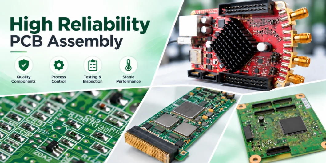
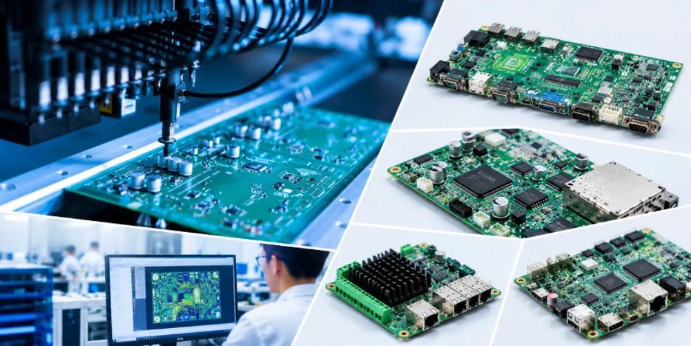
High reliability PCBA examples with heat sinks and RF connectors
Process Controls for Reliable Solder Joints
A reliable joint has the right volume of solder, complete wetting and limited voiding. Each comes from a controlled process step rather than final inspection.
Solder Paste Printing
Most SMT defects begin at the printer. Stencil thickness and aperture design control paste volume; solder paste inspection measures deposit volume and position before placement, so insufficient or bridged deposits are caught before they become joints.
Reflow Profiling
The profile is set for the actual board, with thermocouples on the heaviest and most sensitive components. Large BGAs, thick copper planes and small passives on the same board need a profile that wets all of them without overheating any of them.
Voiding Under Thermal Pads
Voids under QFN and power device thermal pads reduce heat transfer and joint strength. Windowed stencil apertures on large pads, via treatment and profile adjustment reduce voiding, and X-ray measurement confirms the result. If your application has a voiding limit, state it in the requirements.
Moisture, ESD and Cleanliness
Moisture-sensitive devices are handled to their MSL rating and baked when floor life is exceeded, to prevent package cracking during reflow. Flux residues that are acceptable for consumer products can cause leakage or corrosion in humid or high-voltage applications; if the product requires cleaning and ionic cleanliness verification, specify it.
REQUIREMENTS REVIEW · BEFORE QUOTATION
Check That Your Design Can Meet Its Reliability Class
Send the design files and requirement documents. We identify pad, annular ring, through-hole fill and material issues that would prevent Class 3 acceptance.
Include class, environment and test requirements.
Inspection, Test and Board Protection
For high reliability products, inspection and test are planned as layers that each catch what the previous one cannot.
| Method | Detects | Cannot detect |
|---|---|---|
| AOI | Missing, misaligned or wrong-polarity parts, visible bridges and fillets | Joints hidden under packages |
| X-ray | BGA bridging and opens, voiding, through-hole fill | Electrical function, some head-in-pillow conditions |
| Flying probe / ICT | Opens, shorts, wrong component values | Whether the circuit performs its function |
| Functional test | Circuit behaviour against specification | Latent defects that pass at room temperature |
| Burn-in / stress screening | Early-life failures and marginal components | Wear-out mechanisms beyond the screen duration |
Burn-in testing is specified by the customer according to the product’s risk profile; it adds cost and time and is most useful where early-life failures are expensive to find in the field.
Conformal Coating and Mechanical Protection
Boards exposed to humidity, condensation, dust or chemical contamination usually need conformal coating. Specify the coating type, the areas to be masked (connectors, test points, adjustable parts) and the thickness requirement. Heavy components in vibration environments may also need adhesive staking or underfill, which should be shown on the assembly drawing.
Traceability and Change Control
When a high reliability product fails in the field, the investigation depends on the build records. Without them, the only safe response is to treat every unit as suspect.
- Board-level identification: serial number or lot code on every board, linked to the build record.
- Component lot records: date codes and lot numbers of critical components, linked to the board lot. Agree which components require this, because full lot tracking of every passive adds cost.
- Process records: reflow profile, inspection and test results by lot or serial number.
- Change notification: no change to materials, components, process or manufacturing location without customer approval. This is often the most important clause in a high reliability supply agreement.
Our PCB traceability page describes the records that can be kept and how they link to each shipment.
Component Authenticity
Counterfeit or mishandled components are a reliability risk that no assembly process can correct. For high reliability programs, components should be purchased from manufacturers or authorized distributors, with any exception approved by the customer. State this requirement, and any date code or lot recording you need, in the RFQ so it is built into the component sourcing plan for your program.
Qualifying a High Reliability PCBA Manufacturer
A certificate shows that a quality system exists. It does not show how a specific board will be built. During supplier qualification, ask for evidence that applies to your product:
- Certificates for the quality system standard your industry requires, with scope covering PCB assembly.
- How Class 3 acceptance is applied and verified on the line, and how inspectors are trained to the IPC criteria.
- A sample first article report and a sample lot record, to see what evidence ships with each lot.
- How nonconforming product is handled: segregation, disposition, root cause analysis and corrective action.
- The change notification process and how customer approval is recorded.
- Whether the bare board is fabricated in-house or bought, and how bare-board quality is verified in either case.
We recommend qualifying with a first article build on your actual product. The first article and the lot record show how the requirements were applied in practice, which a capability questionnaire cannot. Industry-specific programs are described on our medical PCB assembly and aerospace and defense PCB assembly pages.
High Reliability PCB Assembly FAQ
Is high reliability PCB assembly the same as IPC Class 3?
Class 3 is the most common workmanship requirement in high reliability programs, but reliability also depends on materials, design, process controls, test strategy and traceability. A board can be inspected to Class 3 and still fail early if the laminate or via structure is unsuitable for its thermal environment.
How much more does Class 3 assembly cost?
The increase depends on the board. It comes from tighter process windows, more inspection and rework effort, additional documentation and sometimes design or material changes. Quote both classes if you are deciding which to specify.
Can you build to our own workmanship specification?
Yes, provided it is supplied with the RFQ. Where a customer specification differs from IPC-A-610, the customer document should state which takes precedence.
Do you support lead-containing solder for high reliability products?
Some aerospace, defense and medical products are exempt from RoHS and specify tin-lead solder. State the solder alloy requirement in the RFQ so we can confirm the process and component finishes.
Can the boards be coated and tested before shipment?
Yes. Conformal coating, functional testing and burn-in can be included when specified. Test procedures and pass criteria should be provided or agreed during quotation.
HIGH RELIABILITY PCB ASSEMBLY · RFQ
Quote Your Board to Its Actual Reliability Requirements
Send Gerber/ODB++ files, the BOM, workmanship class, applicable industry standard, test requirements and documentation needs. We review the requirements and confirm scope, price and lead time.
Prototype, qualification and production lots.

Recommended Posts
Expedited PCB Assembly: Lead Times, Readiness and Cost
Highleap Electronics offers expedited PCB assembly for...
Small-Batch High-Mix PCB Assembly for Repeat Orders
Highleap Electronics provides small-batch, high-mix PCB...
EVT DVT and PVT PCB Assembly: From Validation to Production
Highleap Electronics supports EVT, DVT and PVT PCB...
Prototype PCB Assembly: From Design Files to Tested Boards
Highleap Electronics builds prototype PCB assemblies for...
How to get a quote for PCBs
Let‘s run DFM/DFA analysis for you and get back to you with a report. You can upload your files securely through our website. We require the following information in order to give you a quote:
-
- Gerber, ODB++, or .pcb, spec.
- BOM list if you require assembly
- Quantity
- Turn time
In addition to PCB manufacturing, we offer a comprehensive range of electronic services, including PCB design, PCBA, and turnkey solutions. Whether you need help with prototyping, design verification, component sourcing, or mass production, we provide end-to-end support to ensure your project’s success.
For PCBA services, please provide your BOM (Bill of Materials) and any specific assembly instructions. We also offer DFM/DFA analysis to optimize your designs for manufacturability and assembly, ensuring a smooth production process.