
Color and Alphanumeric Value Coding of Capacitor
Capacitors use several marking systems to indicate capacitance, tolerance, voltage rating, polarity, and other electrical characteristics. Depending on the capacitor type, you may see color bands, a three-digit code such as 104 or 472, a direct value such as 4.7µF, or a combination of letters and numbers.
Correctly reading these capacitor codes and markings is important when selecting replacement components, checking a schematic or BOM, troubleshooting an existing circuit, or preparing components for PCB assembly. A capacitor with the correct nominal capacitance but the wrong voltage rating, dielectric, package, tolerance, or polarity may still be unsuitable for the circuit.
Quick Reference for Common Capacitor Codes
One of the most common capacitor marking systems uses three digits. The first two digits are the significant figures, and the third digit indicates how many zeros should be added. The resulting value is normally expressed in picofarads (pF).
| Capacitor Code | Value in pF | Value in nF | Value in µF |
|---|---|---|---|
| 101 | 100 pF | 0.1 nF | 0.0001 µF |
| 102 | 1,000 pF | 1 nF | 0.001 µF |
| 103 | 10,000 pF | 10 nF | 0.01 µF |
| 104 | 100,000 pF | 100 nF | 0.1 µF |
| 105 | 1,000,000 pF | 1,000 nF | 1 µF |
| 224 | 220,000 pF | 220 nF | 0.22 µF |
| 472 | 4,700 pF | 4.7 nF | 0.0047 µF |
| 474 | 470,000 pF | 470 nF | 0.47 µF |
For example, a capacitor marked 104 represents 10 followed by four zeros in picofarads:
100,000 pF = 100 nF = 0.1 µF.
Color Coding of Capacitors
Color bands are mainly found on older leaded ceramic, film, molded, and other legacy capacitor types. Depending on the capacitor and coding system, the bands can represent significant digits, a capacitance multiplier, tolerance, working voltage, or other characteristics.
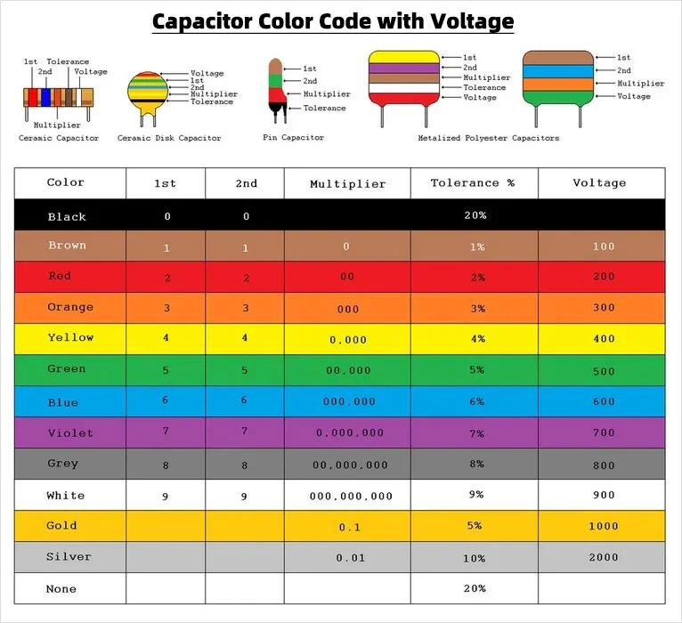
The capacitor color code chart below provides a visual reference for interpreting common capacitor color bands. Start with the significant digits and multiplier, then check whether additional bands are used for tolerance, voltage, or another parameter.
Deciphering the Color Bands
In a common capacitor color-code system, the first two colors represent significant digits and the following color acts as a multiplier. The resulting capacitance is typically calculated in picofarads.
| Color | Digit | Multiplier |
|---|---|---|
| Black | 0 | ×1 |
| Brown | 1 | ×10 |
| Red | 2 | ×100 |
| Orange | 3 | ×1,000 |
| Yellow | 4 | ×10,000 |
| Green | 5 | ×100,000 |
| Blue | 6 | ×1,000,000 |
| Violet | 7 | ×10,000,000 |
| Gray | 8 | ×100,000,000 |
| White | 9 | ×1,000,000,000 |
For example, if a capacitor follows this coding convention and its significant-value bands are red (2) and violet (7), followed by green as the multiplier (×100,000), the nominal capacitance is:
27 × 100,000 pF = 2,700,000 pF = 2,700 nF = 2.7 µF.
Interpreting Tolerance and Voltage Ratings
Additional color bands may indicate capacitance tolerance, working voltage, temperature coefficient, or other characteristics. The exact convention is not identical across every legacy capacitor family, so the color chart should be used together with the relevant capacitor specification whenever possible.
When identifying an older capacitor for repair, replacement, or production, confirm the value against the manufacturer’s datasheet, schematic, BOM, or original part number rather than relying only on the visible bands.
Alphanumeric Value Coding of Capacitors
Alphanumeric capacitor markings are common on many modern leaded and larger packaged capacitors. The capacitance may be printed directly or represented by a three-digit code.
Common examples of direct markings include:
- 100p = 100 pF
- 4n7 = 4.7 nF
- 22n = 22 nF
- 100n = 100 nF = 0.1 µF
- 2u2 = 2.2 µF
- 10u = 10 µF
How to Read a 3-Digit Capacitor Code
For a common three-digit capacitor code, the first two digits are the significant figures and the third digit is the number of zeros to add. The result is normally expressed in picofarads.
First two digits × 10third digit pF
Examples:
- 102 = 1,000 pF = 1 nF
- 103 = 10,000 pF = 10 nF
- 104 = 100,000 pF = 100 nF = 0.1 µF
- 222 = 2,200 pF = 2.2 nF
- 472 = 4,700 pF = 4.7 nF
- 223 = 22,000 pF = 22 nF
- 224 = 220,000 pF = 220 nF = 0.22 µF
- 474 = 470,000 pF = 470 nF = 0.47 µF
- 105 = 1,000,000 pF = 1 µF
What Does 104 Mean on a Capacitor?
The 104 capacitor code means:
10 × 10,000 pF = 100,000 pF = 100 nF = 0.1 µF.
A 0.1 µF capacitor is commonly used for decoupling, bypassing, filtering, and other general circuit functions. However, the marking 104 identifies only the nominal capacitance. It does not by itself identify the voltage rating, tolerance, dielectric, package size, or temperature characteristics.
What Does 472 Mean on a Capacitor?
A 472 capacitor has a nominal capacitance of:
47 × 100 pF = 4,700 pF = 4.7 nF = 0.0047 µF.
This conversion is useful when a schematic specifies the capacitor in nanofarads while the physical component uses a three-digit marking.
Capacitor Tolerance Codes
Capacitor tolerance indicates how far the actual capacitance may vary from the stated nominal value. Letter codes are commonly used on many capacitor families.
| Tolerance Code | Capacitance Tolerance |
|---|---|
| F | ±1% |
| G | ±2% |
| J | ±5% |
| K | ±10% |
| M | ±20% |
For example, 104K generally indicates a 100 nF capacitor with ±10% capacitance tolerance, while 104J indicates the same nominal value with ±5% tolerance.
How to Read Capacitor Voltage Ratings
Voltage rating is just as important as capacitance. It indicates the maximum rated voltage for which the capacitor is designed under specified operating conditions.
On larger electrolytic and film capacitors, the voltage is often printed directly, such as 10µF 25V, 100µF 50V, or 1µF 450V. Smaller capacitors may use manufacturer-specific voltage codes, while many small surface-mount ceramic capacitors do not display a voltage rating on the component body.
When replacing or sourcing a capacitor, do not select a part only because its capacitance matches. The voltage rating, dielectric, tolerance, operating temperature, ESR, ripple-current capability, package, polarity, and circuit requirements may all affect whether the replacement is suitable.
Special Considerations for Different Capacitor Types
Ceramic Capacitors and MLCCs
Leaded ceramic capacitors may use three-digit capacitance markings, while many small multilayer ceramic capacitors (MLCCs) used in SMT production have no readable marking at all.
For production, MLCCs should therefore be identified from the BOM, manufacturer part number, reel label, package size, dielectric specification, and approved component data rather than by visual inspection alone.
Aluminum Electrolytic Capacitors
Aluminum electrolytic capacitors usually display capacitance and rated voltage directly on the body. Because they are polarized, correct orientation is essential during PCB assembly.
The negative terminal is commonly identified by a stripe on the capacitor body. The component datasheet, PCB polarity markings, assembly drawing, and BOM should agree before production.
Tantalum and Polymer Capacitors
Tantalum and many polymer capacitors are also polarized. Their polarity and marking conventions can differ from those used on aluminum electrolytic capacitors, so the manufacturer’s datasheet should be checked before approving an alternate part or releasing the assembly to production.
Film Capacitors
Film capacitors often have enough body area to display capacitance, tolerance, rated voltage, series information, and safety approvals directly. Some older film capacitors may also use color-band coding.
Capacitor Color Code Example
The easiest way to understand capacitor color coding is to work through an example. The image below illustrates how the significant-digit and multiplier bands are used to determine the nominal capacitance.
For example, consider a capacitor whose first three capacitance bands are:
- Yellow — first digit: 4
- Red — second digit: 2
- Orange — multiplier: ×1,000
The calculation is:
42 × 1,000 pF = 42,000 pF = 42 nF = 0.042 µF.
The nominal capacitance represented by these three bands is therefore 42 nF. If additional bands are present, they may indicate tolerance, voltage rating, temperature coefficient, or another characteristic depending on the capacitor type and coding system.
This is also why capacitor identification should not stop at nominal capacitance. For an actual PCB design or replacement BOM, tolerance, rated voltage, dielectric, package, polarity, and application requirements should also be verified.
Common Pitfalls When Interpreting Capacitor Codes
Misreading Color Codes Due to Poor Visibility
Older capacitors may have faded, discolored, or contaminated color bands. Brown can be confused with red, while blue and violet may become difficult to distinguish under poor lighting.
If the component affects circuit safety or reliability, visual identification should be confirmed against the schematic, BOM, original part number, or appropriate electrical measurement.
Confusing µF, nF, and pF
Incorrect unit conversion is one of the most common capacitor identification errors.
- 1 nF = 1,000 pF
- 1 µF = 1,000 nF
- 1 µF = 1,000,000 pF
For example, 100,000 pF = 100 nF = 0.1 µF.
Overlooking Voltage Rating and Tolerance
Finding the capacitance value does not mean that the capacitor has been fully identified. A 0.1 µF capacitor rated for 16 V is not automatically interchangeable with a 0.1 µF capacitor rated for 100 V, and a ±20% part may be unsuitable where the circuit requires ±5% tolerance.
Assuming Every SMD Marking Is a Capacitor Value
Not every number printed on a surface-mount component follows a universal capacitance code. In addition, many small MLCCs are completely unmarked.
For production PCB assembly, the BOM and manufacturer part number should take priority over attempting to identify an SMD capacitor only from its visible surface.
Miscalculating Multiplier Codes
A code such as 104 means 10 followed by four zeros in picofarads, not 104 pF. Similarly, 472 means 47 followed by two zeros, or 4,700 pF.
Assuming a Standard Tolerance
If the tolerance is not explicitly marked, do not automatically assume ±5%, ±10%, or ±20%. Check the component specification or manufacturer part number whenever tolerance is important to circuit performance.
Selecting the Right Capacitor for a PCB
Reading the capacitor code answers only one part of the selection process. For an actual PCB design or production BOM, engineers and sourcing teams usually need to evaluate several additional parameters.
Capacitance and Tolerance
The nominal capacitance must match the circuit requirement, while tolerance determines the acceptable variation around that value. Tight-tolerance capacitors may be particularly important in timing, filtering, sensing, and precision analog circuits.
Voltage Rating
The capacitor must have an appropriate rated voltage for normal circuit operation, expected transients, and the design’s required derating policy.
Dielectric and Capacitance Stability
For ceramic capacitors, dielectric type affects capacitance stability with temperature and applied DC voltage. C0G/NP0 capacitors are commonly used where stability is important, while X7R and X5R are widely used where higher capacitance density is required.
ESR and Ripple Current
Equivalent series resistance and ripple-current capability can be important in power supplies, converters, filtering circuits, and other applications with significant AC current.
Package Size and PCB Footprint
The capacitor package must match the PCB footprint and assembly process. This is especially important when replacing an obsolete component or qualifying an alternate manufacturer part number.
Polarity
Electrolytic, tantalum, and other polarized capacitors must be installed in the correct orientation. Polarity should be clearly defined in the PCB silkscreen, BOM, assembly drawing, and production documentation.
Availability and Lifecycle
A capacitor can be electrically suitable but still create production problems if it is obsolete, difficult to source, or available only with an unacceptable lead time.
For projects moving from design into production, component availability should be reviewed together with the electrical specification. Highleap Electronics provides electronic component sourcing services for passive components, ICs, connectors, and other BOM items required for PCB assembly.
Capacitor Identification in PCB Assembly
In prototype and production PCB assembly, capacitor identification cannot rely only on what is printed on the component body. The assembly team needs to match the BOM specification with the correct manufacturer part number, footprint, reference designator, package, polarity, and electrical requirements.
Typical capacitor-related checks before PCB assembly include:
- Capacitance value and tolerance
- Rated voltage
- Manufacturer and manufacturer part number
- Approved alternate components
- MLCC dielectric and package size
- Electrolytic or tantalum capacitor polarity
- PCB footprint compatibility
- Component height and mechanical clearance
- Operating temperature requirements
- Availability and component lifecycle
These checks are especially important when a prototype moves into repeat or volume production. An incorrect substitute may fit the footprint and even pass an initial power-on test while still affecting circuit performance, manufacturability, or long-term reliability.
SMD Capacitors in SMT PCB Assembly
Modern PCB assemblies commonly use large numbers of SMD ceramic capacitors for decoupling, filtering, signal conditioning, timing, and power management. During SMT production, these components are placed automatically from reels according to the approved BOM and pick-and-place data.
You can learn more about solder paste printing, component placement, reflow soldering, AOI, X-ray inspection, and related production stages in our SMT equipment and process overview.
Highleap Electronics provides PCB assembly services covering component sourcing, SMT placement, through-hole assembly, inspection, testing, and related PCBA processes for prototypes and production builds.
From Capacitor Selection to PCB Production
For an engineer or technician, capacitor identification may begin with a simple question such as “What does 104 mean?” Once the design moves toward production, however, the more important issue is whether the selected component is suitable, available, correctly documented, and compatible with the PCB manufacturing and assembly process.
Highleap Electronics can support the manufacturing flow from PCB fabrication and BOM procurement to SMT, through-hole assembly, inspection, and testing.
For customers who prefer a single supplier to manage the complete manufacturing chain, our turnkey PCB assembly service combines PCB fabrication, electronic component sourcing, PCB assembly, and testing in one workflow.
Send Highleap Electronics your Gerber files, BOM, and production requirements. We support component sourcing, PCB fabrication, SMT and through-hole assembly, inspection, and testing from prototype to volume production.
Frequently Asked Questions About Capacitor Codes
What does 104 mean on a capacitor?
A capacitor marked 104 has a nominal capacitance of 100,000 pF, which equals 100 nF or 0.1 µF.
What does 472 mean on a capacitor?
A capacitor marked 472 has a nominal capacitance of 4,700 pF, which equals 4.7 nF or 0.0047 µF.
What does K mean on a capacitor?
When K is used as a capacitance tolerance code, it generally indicates ±10%. J commonly indicates ±5%, while M commonly indicates ±20%.
How do I identify an unmarked SMD capacitor?
For an unmarked SMD capacitor, start with the PCB BOM, schematic, reference designator, manufacturer part number, and original reel or packaging information. An LCR meter may help confirm approximate capacitance during troubleshooting, but measurement alone usually cannot identify the complete component specification.
Are capacitor color codes the same as resistor color codes?
The numerical color sequence is similar in some legacy capacitor coding systems, but capacitor band functions are not universally identical to resistor codes. Additional bands may represent tolerance, voltage, temperature characteristics, or other information.
Can I replace a capacitor with another capacitor of the same value?
Not necessarily. In addition to capacitance, compare voltage rating, tolerance, dielectric, ESR, ripple-current capability, temperature rating, polarity, package size, and application requirements.
Why are many SMD ceramic capacitors unmarked?
Small MLCC packages have very limited surface area, and body markings are often unnecessary in automated production. PCB assembly factories identify these components through controlled BOM data, manufacturer part numbers, reel labels, and material traceability.
What information should I provide for a PCB assembly quotation?
For a PCB assembly quotation, provide your Gerber or PCB production files, BOM with manufacturer part numbers where available, required quantity, and any relevant assembly or testing instructions. These files allow the manufacturer to review PCB fabrication, component procurement, assembly, and testing requirements before production.
Conclusion
Correctly reading capacitor color codes, three-digit capacitor codes, tolerance markings, and voltage ratings helps avoid errors during component identification, troubleshooting, design verification, and BOM preparation. Common markings such as 104 and 472 are straightforward once the multiplier system is understood, but capacitance alone does not define the complete capacitor specification.
When a design moves into production, the capacitor must also match the required voltage, tolerance, dielectric, package, polarity, operating conditions, lifecycle, and PCB footprint. Component sourcing and PCB assembly therefore need to be considered together rather than as separate steps.
If your PCB design and BOM are ready, Highleap Electronics can provide PCB fabrication, electronic component sourcing, and PCB assembly from prototype through volume production. Send your Gerber files and BOM for a PCB & PCBA quotation →

Recommended Posts
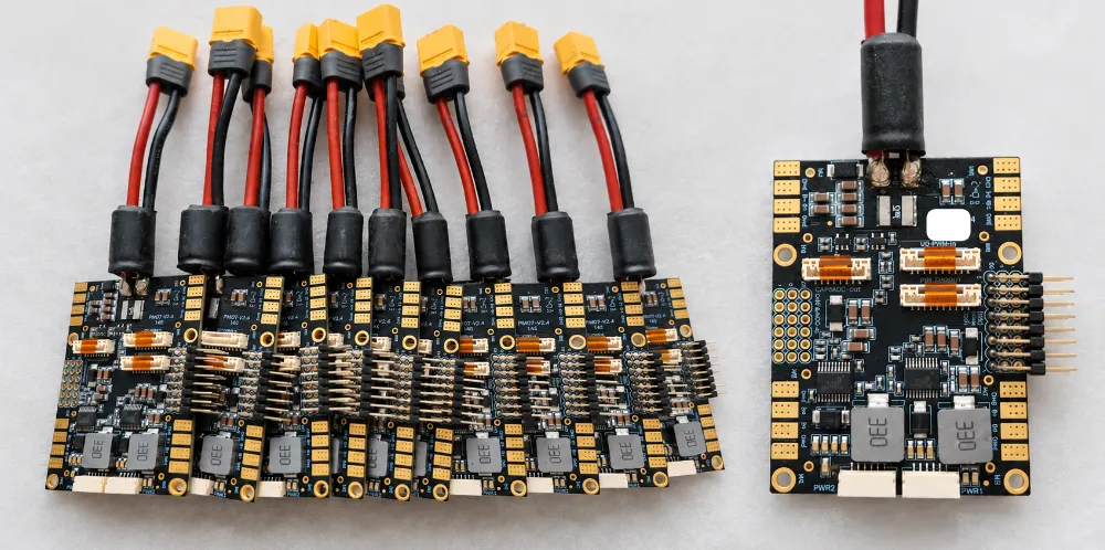
Drone Flight Control Power Distribution Board
Figure 1. Drone Flight Control Power Distribution BoardIf...
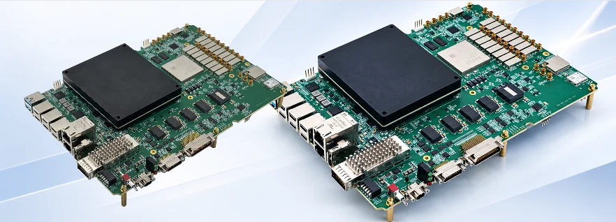
High-Speed RFSoC PCB Manufacturing and Assembly: Key Engineering Considerations
How to get a quote for PCBs Let's run DFM/DFA analysis for...
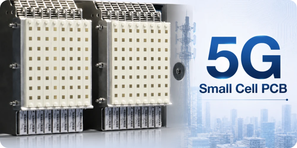
5G Small Cell PCB Manufacturing for RF and Telecom Infrastructure
Table of Contents 5G Small Cell PCB Requirements Depend on...
Custom 65% Keyboard PCB and PCBA Manufacturing
Table of contents 1. From Design Files to Production-Ready...