
Custom Bluetooth Speaker PCB Board Solutions

Table of Contents
- Three Electrical Environments on One Board
- PCB Board Specifications for Bluetooth Speakers
- Component Placement: Eight Rules That Determine Audio Quality
- Power Rail Architecture and Decoupling
- PCB Trace Antenna vs. Chip Antenna
- Failure Diagnosis: Symptom, Root Cause, Fix
- Highleap’s PCB Board Fabrication for Bluetooth Speakers
- Frequently Asked Questions
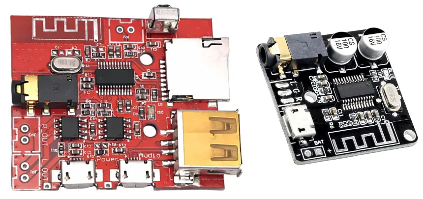
The Bluetooth speaker PCB board manages three incompatible electrical environments at once — RF at 2.4 GHz, microvolt analog audio, and a noisy battery power supply — all on a board typically smaller than a business card. Every major audio quality problem, wireless dropout, and certification failure traces back to how those three environments are isolated from each other on the board.
This guide focuses on the physical design decisions: specifications, placement rules, power architecture, antenna selection, and the failure modes that appear when any of these is done wrong. For a component-by-component overview of what a Bluetooth Speaker PCB contains, see our main resource on the topic.
1) Three Electrical Environments on One Board
A standard consumer electronics board handles one dominant signal type. A Bluetooth speaker PCB board handles three simultaneously — and they actively interfere with each other if the layout does not account for each.
| Environment | Signal Level / Frequency | Layout Threat | Consequence If Ignored |
|---|---|---|---|
| RF (Bluetooth) | 2.4 GHz, −90 dBm receive sensitivity | Ground copper inside antenna keepout; battery near antenna | Short range, dropouts, FCC/CE failure |
| Analog audio | 20 Hz–20 kHz, microvolt to millivolt levels | Shared ground return with Class D switching; power supply noise coupling | Audible hiss, hum, or buzz at idle |
| Battery power | 2.7–4.2V, switching transients at 300–500 kHz | Undersized decoupling; shared supply rails between digital and analog | Power supply noise in audio; volume drop as battery discharges |
The layout must physically separate these three zones. RF section stays at one board corner near the edge. Audio amplifier and output filter stay at the opposite end. Power supply rails run between them with adequate decoupling at every zone boundary.
2) PCB Board Specifications for Bluetooth Speakers
| Parameter | Standard (≤5W) | Higher-Performance (>5W or certification required) |
|---|---|---|
| Layer count | 2-layer | 4-layer |
| Board material | FR4, Tg 130°C | FR4, Tg 150°C minimum |
| Finished thickness | 1.6 mm | 1.0 mm or 0.8 mm for compact enclosures |
| Copper weight | 1 oz all layers | 1 oz signal layers; 2 oz on amplifier power layer |
| Min. trace/space | 5 mil / 5 mil | 3 mil / 3 mil for QFN/WLCSP Bluetooth SoC pads |
| Surface finish | HASL (through-hole only) | ENIG — required for all QFN/WLCSP packages |
| Min. via: drill / pad | 0.3 mm / 0.6 mm | 0.2 mm / 0.4 mm for high-density designs |
| Controlled impedance | Not required | 50Ω microstrip on antenna feed trace only |
For boards thinner than 1.6 mm, confirm with your fabricator that the USB-C connector footprint includes reinforced strain relief pads. Thin boards (0.8 mm) under repeated plugging cycles develop pad cracking that creates intermittent charging faults in production.
3) Component Placement: Eight Rules That Determine Audio Quality
Placement order matters as much as the rules. Place in this sequence: Bluetooth SoC first, then audio amplifier, then battery management IC, then passives around each.
- Bluetooth SoC at a board corner, near the antenna edge. The SoC’s antenna port must connect to the antenna structure with the shortest possible trace — ideally under 5 mm. Every millimeter of additional routing adds insertion loss and antenna detuning risk.
- Audio amplifier minimum 20 mm from the Bluetooth SoC. Class D amplifiers (TI TAS3251, TI TAS5822) switch at 300–500 kHz and generate magnetic fields that couple into the SoC’s RF front end at distances under 20 mm. This degrades Bluetooth receive sensitivity.
- Battery management IC near the charging port, away from audio. The BQ25895 and similar PMICs switch at up to 1.5 MHz during fast charging. Place within 10 mm of the USB-C connector and at least 30 mm from the audio amplifier output stage.
- Output filter inductors oriented perpendicular to each other. The two inductors in the Class D output filter (L+ and L−, typically 4.7–10 µH) should be rotated 90° relative to each other to cancel mutual inductance. Parallel orientation couples switching energy between them and increases output ripple.
- Decoupling capacitors within 0.5 mm of every IC power pin. The 100 nF ceramic must be on the same layer as the IC, connected with a trace under 1 mm before reaching the via. Longer traces defeat the decoupling at frequencies above 50 MHz.
- Crystal oscillator directly adjacent to the SoC crystal pins. Crystal and load capacitors belong within 3 mm of the SoC, surrounded by a ground ring. Crystal traces longer than 10 mm radiate at the crystal frequency and commonly cause FCC test failures.
- Button input traces routed away from audio signal traces. Button traces carry mechanical switching transients. Keep them on the opposite board edge from the audio output filter and do not route them parallel to audio signal traces.
- LED circuitry at the board perimeter. LED driver currents share the VCC rail with the SoC. Place current-limiting resistors within 3 mm of the LEDs, not near the SoC power section.
For how these placement decisions translate into assembly yield and audio consistency, the audio PCB assembly guide covers the manufacturing view of these layout choices.
4) Power Rail Architecture and Decoupling
A typical Bluetooth speaker needs three regulated supply rails from a single Li-ion cell (2.7–4.2V nominal).
| Rail | Typical Target | Converter Type | Critical Note |
|---|---|---|---|
| Bluetooth SoC core | 1.8V or 3.3V | LDO from VBAT | LDO provides better noise rejection than DCDC for sensitive RF/analog sections |
| Audio amplifier | 5V regulated | Synchronous boost DCDC | Without boost, output power drops ~50% as battery discharges from 4.2V to 3.0V |
| VBAT direct | 2.7–4.2V (raw) | Direct via PMIC | Charging circuit only — never connect SoC or audio ICs directly to raw VBAT |
The 100 nF ceramic capacitor handles 1 MHz to several hundred MHz. The 10 µF bulk capacitor handles the 10–100 kHz range from Class D switching transients. Both are needed — neither alone is sufficient.
Route power traces from the converter output through the bulk capacitor, then to the IC VCC pin, then to the 100 nF capacitor — all in a linear path. Branching power traces before the decoupling capacitors defeats their purpose and is the most common power supply routing mistake on Bluetooth speaker PCB boards.
For detailed Class D amplifier PCB layout guidance including power stage routing and thermal management, see our amplifier-specific resource.
5) PCB Trace Antenna vs. Chip Antenna
| Factor | PCB Trace Antenna (inverted-F / meander) | Chip Antenna (SMT ceramic) |
|---|---|---|
| Component cost | $0 (copper only) | $0.10–$0.30 per unit at volume |
| Board area required | ~5 × 15 mm keepout zone, all layers | ~3 × 8 mm typical |
| RF performance | Slightly better peak gain when tuned correctly | Slightly lower gain; acceptable for 10 m range |
| Tuning complexity | Must be recalculated if board size or substrate changes | Matching network required; easier to port across board revisions |
| Keepout rule | No copper on any layer within keepout — including inner layers of 4-layer boards | Same principle; smaller zone |
| Best for | Cost-sensitive high-volume designs with fixed board dimensions | Compact enclosures; frequent design revisions; early prototypes |
Regardless of antenna type: the antenna must face the exterior of the speaker enclosure. A board mounted with the antenna facing internal battery cells degrades effective radiated power by 6–10 dB. This is a mechanical decision that must be locked at enclosure design time — it cannot be corrected in firmware.
For RF module integration and Wi-Fi coexistence beyond the speaker PCB board level, the Bluetooth PCB module overview covers matching networks and 2.4 GHz coexistence management.
6) Failure Diagnosis: Symptom, Root Cause, Fix
| Symptom | Most Likely Root Cause | Fix |
|---|---|---|
| Audible hiss or buzz at idle | Ground plane split or high-impedance return path coupling Class D switching into audio signal | Ensure continuous ground plane; use star ground connection between sections |
| Bluetooth drops out beyond 3–4 meters | Ground copper inside antenna keepout zone; antenna facing into enclosure | Remove all copper from keepout on all layers; verify antenna orientation |
| Volume drops as battery reaches 40% | Amplifier powered from raw VBAT with no boost; output power proportional to VBAT² | Add synchronous boost converter (5V output); TI TPS61088 or equivalent |
| USB-C charging intermittent after 200–500 insertions | Insufficient connector pad anchoring on thin (0.8 mm) board | Add through-hole anchoring legs or side-wall solder tabs on connector body |
| FCC Part 15B or CE radiated emission failure | Crystal trace too long; USB VBUS cable acting as emission antenna; output filter too far from amplifier | Shorten crystal traces; add common-mode filter on VBUS; move output filter inductors within 5 mm of amplifier output pins |
| One audio channel silent or distorted | Insufficient solder paste on Class D output stage differential pad; one output pin not wetted | Adjust stencil aperture; verify reflow reaches 245°C minimum at amplifier body; add AOI for pin wetting |
7) Highleap’s PCB Board Fabrication for Bluetooth Speakers
Highleap Electronics fabricates PCB boards for Bluetooth speaker designs, from prototype to production volume:
- 2-layer and 4-layer FR4 — 1.6 mm standard; custom thicknesses from 0.6 mm to 2.4 mm
- ENIG surface finish — standard for QFN and WLCSP Bluetooth SoC packages
- Controlled impedance — 50Ω microstrip for antenna feed traces; TDR verification included
- 3 mil/3 mil minimum trace/space — supports 0.4 mm pitch QFN packages
- DFM review before production — checks antenna keepout zone, decoupling placement, connector pad geometry
- Prototype turnaround 3–5 business days — standard FR4 specifications
For complete turnkey service including SMT assembly of the Bluetooth SoC and audio amplifier, see our PCB assembly service. For bare board production specifications, see our PCB fabrication page. For how speaker PCB boards integrate into complete audio system designs, our speaker PCB systems resource covers crossover, amplifier, and multi-driver configurations.
Request a Bluetooth Speaker PCB Board Quote
Frequently Asked Questions
What layer count does a Bluetooth speaker PCB board need?
2-layer boards work for simple designs at 5W or less without certification requirements. 4-layer boards are needed for designs above 5W, FCC/CE certification, or designs with a DSP or USB audio interface. The 4-layer stack — signal / ground / power / signal — provides the continuous low-impedance ground reference that separates the RF and audio sections effectively.
Why must the Bluetooth antenna keepout zone be copper-free on all layers?
The 2.4 GHz antenna radiates in three dimensions. Ground copper on any layer within the keepout zone — including the inner ground plane of a 4-layer board — acts as a parasitic element that detunes the antenna and reduces radiated efficiency. The keepout must be applied to all layers in the PCB editor, not just the top copper layer. Most first-time designers apply it only to the top layer and discover the problem during pre-certification RF testing.
How much separation is needed between the Bluetooth SoC and the Class D amplifier?
20 mm minimum. Class D switching frequencies (300–500 kHz) and their harmonics extend into the 2.4 GHz band and degrade the SoC’s receive sensitivity at shorter distances. On a small board where 20 mm is not achievable, place a continuous ground pour between the two ICs to provide partial shielding.
Does the Bluetooth speaker PCB board need an impedance-controlled trace?
Only the RF feed trace from the SoC’s antenna port to the antenna structure requires impedance control — designed as a 50Ω microstrip. All other traces (audio signals, power supply, button inputs, LED drives) do not require controlled impedance at their operating frequencies.
What is the most common Bluetooth speaker PCB board design failure?
Ground copper inside the antenna keepout zone is the most common layout problem in DFM reviews. The second most frequent issue is decoupling capacitors placed 2–5 mm from IC power pins rather than within the effective maximum of 0.5–1 mm. Both are easy to correct at DFM stage and expensive to fix after prototype testing.

Recommended Posts

Custom Rogers RO4835 PCB Fabrication & Assembly Services
Figure 1. Rogers RO4835 PCBRogers RO4835 PCB is a...

Nelco N4000-13 PCB Material and Manufacturing Guide | Highleap Electronics
Figure 1. Nelco N4000-13 PCBNelco N4000-13 PCB is a...

Rogers RT/duroid 6002 PCB Manufacturer — Specifications, Stackup, Quote
Figure 1. Rogers RT/duroid 6002Rogers RT/duroid 6002 is...

Miniaturize Antennas with Rogers TMM Laminates
Figure 1. Rogers TMM Executive Summary: Rogers TMM...
How to get a quote for PCBs
Let us run DFM/DFA analysis for you and get back to you with a report.
You can upload your files securely through our website.
We require the following information in order to give you a quote:
-
- Gerber, ODB++, or .pcb, spec.
- BOM list if you require assembly
- Quantity
- Turn time