
Portable Thermal Camera PCB Design and PCBA Manufacturing Guide
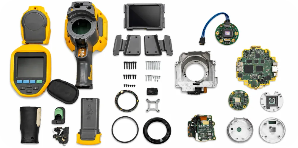
The thermal imaging module is often the part of a handheld infrared camera that a buyer cannot afford to damage during rework. Yet a quotation for a portable thermal camera PCB may cover only the host board, leaving module procurement, socket installation and post-assembly verification outside the quoted price. For an OEM comparing thermal imaging PCB assembly suppliers, those omissions matter more than a small difference in bare-board cost.
Highleap Electronics provides PCB fabrication, component sourcing and PCBA assembly for many types of electronic hardware. For an infrared camera controller or thermal sensor carrier, the manufacturing discussion begins with the actual PCB construction, approved component list and installation sequence. The same factory services also apply to industrial controllers, communication equipment and other OEM electronics; each board receives a process based on its released design.
Is the Uncooled Microbolometer Included in Your PCBA Quote?
For a thermal camera module carrier PCB, the critical purchase may be a socket-mounted uncooled microbolometer or an integrated thermal imaging core. A different design may place a sensor interface on one board and the image-processing electronics on another. Neither the word “camera” nor the total component count tells the assembler whether the expensive module will be supplied, installed or tested.
Define the installation point before the soldering process is approved
Some thermal modules attach through a manufacturer-specified socket; others have different mounting or processing restrictions. The OEM should provide the module’s exact part number, mechanical drawing and supplier handling instructions. When the approved method calls for installation after board reflow, a base-PCBA electrical screen may be possible before the core is fitted. That can reduce exposure of costly components to rework, although the sequence must suit the actual design and test access.
For OEM infrared camera PCB assembly, the purchase order should identify three separate responsibilities: who sources the module, who performs the approved attachment step, and who pays for or evaluates a failed module. Record incoming condition and serial-number association when traceability is required. This is a more useful comparison between suppliers than asking each for a single unexplained “thermal camera PCBA” price.
Your Processor Heat Path Can Change the Sensor’s Environment
A handheld thermal camera can combine a warm image processor, a battery charger, a display and a temperature-sensitive sensor in one small housing. Even if the processor stays within its component temperature limit, heat conducted through PCB copper or the chassis may change the thermal environment around the imaging core.
Protect the validated heat path, not just the processor
For a portable infrared camera PCB manufacturing project, the released layout may specify thermal-via arrays, copper pours, component keep-outs or contact pads for a heat spreader. A fabrication change that improves one device’s cooling could unintentionally bring heat closer to the module. Our discussion of PCB heat-spreading and thermal-via methods provides useful background, but the thermal-camera assembly must follow the approved board geometry and mechanical heat path.
A manufacturing review should flag any proposed change to the stack-up, copper balance, charger placement or thermal-interface lands. The product owner should then evaluate its effect during warm-up, continuous imaging and charging, as applicable. Board fabrication and PCBA inspection can verify the specified construction; they cannot independently certify radiometric accuracy inside the completed enclosure.
When a Camera FPC Connector Fits the PCB but Not the Enclosure
A miniature FPC socket can be soldered in the correct location and still prevent the display cable from being inserted once the infrared camera housing is closed. Mating direction, latch access, connector height and the bend direction of the flex all affect assembly. These are practical constraints for buyers searching for camera FPC and thermal sensor PCB assembly, not minor finishing details.
For designs with separate display, sensor or control flexes, provide a side-view drawing and cable insertion direction alongside the placement file. The camera FPC interconnect options are relevant when the approved board set includes a flexible connection; the factory should not add a flex circuit to a design that uses ordinary connectors or cables.
The same physical review should cover optical-axis datums, mounting-hole position, standoff height and whether the sensor is installed before or after enclosure assembly. A first-article mechanical fit check can identify a connector mismatch before repeat orders, even when electrical continuity has passed.
Two Thermal Imaging Boards Can Need Different Assembly Routes
A small infrared sensor carrier with a socket and a few passives does not necessarily need the same production process as a processor-heavy thermal imaging camera controller PCBA with external memory, power-management devices, USB and high-speed image interfaces. The latter may require multilayer impedance control or advanced package inspection; the former may be governed mainly by socket alignment and module handling.
Fine-pitch assembly is selected by package risk
For a high-density thermal camera PCB, the approved processor footprint, BGA escape, QFN thermal pads and memory routing determine fabrication and SMT requirements. Where hidden solder joints warrant it, X-ray examination of BGA solder connections may supplement optical inspection. Neither BGA packaging nor a thermal camera label automatically means the board needs HDI or X-ray on every unit.
Highleap’s electronic manufacturing services for customer-defined PCBAs cover different product sectors and assembly requirements. For programs needing one supplier to coordinate approved board fabrication, component purchasing and PCB assembly, the turnkey PCB assembly option can be discussed. Expensive imaging cores, cable attachment, firmware programming and any special inspections should be included in that quotation only where expressly agreed.
Highleap Electronics • Your PCB & PCBA Manufacturing Partner
One-Stop PCB & PCBA Service. Worldwide Delivery.
Simplify your next electronics order with coordinated PCB fabrication, approved component sourcing and assembly. Ask Highleap for a tailored quotation and discuss delivery, ongoing support and payment arrangements before placing your order.
✓ One-Stop PCB/PCBA Manufacturing
✓ Worldwide Shipping Options
✓ Extended After-Sales Support
✓ Flexible Payment Options
| Get My Quote | Discuss My Order |
Shipping arrangements, after-sales coverage and payment terms are confirmed for each order.
A Thermal Image Is Not Proof of Temperature Accuracy
For thermal camera PCBA functional testing, seeing a live infrared image proves that at least part of the power, processor and sensor data path works. It does not prove the instrument measures temperature accurately. Procurement specifications should keep these acceptance stages separate instead of asking the PCB factory for an undefined “100% thermal test.”
A board-level test plan can define the following checks, depending on the actual circuit and supplied fixture:
- Before core installation, when feasible: verify power rails, boot and memory behavior without risking the imaging module.
- After core installation: identify the sensor, confirm its communication link and check for the specified image-data output or diagnostic response.
- Configuration control: verify the approved firmware and record the module or PCBA serial association when required by the OEM.
FFC and radiometric calibration are not interchangeable
Some thermal cores perform flat-field correction (FFC) or non-uniformity correction to improve image uniformity. A calibrated temperature reading, by contrast, can depend on optics, target emissivity, enclosure temperature, the thermal window and the product’s compensation method. If a factory-run radiometric check is required, the OEM must define the calibrated target, conditions, equipment, procedure and pass/fail limits. Routine electrical inspection alone cannot establish finished-camera measurement accuracy.
Lock the Accepted Build Before the Next Production Order
For prototype-to-production thermal imaging PCBA, an accepted image on a pilot unit should be accompanied by records that let the same assembly be reproduced. The documents that matter most are not generic certificates; they are the approved imaging-core revision, the board and BOM revisions, and the test configuration that established acceptance.
Before placing a repeat order, ask the supplier to preserve:
- Core and sourcing status: thermal-module part number, supply ownership, approved substitutes, incoming handling and serialized tracking where specified.
- Mechanical and assembly record: socket or FPC orientation, installation stage, reflow restrictions and any first-article fit or solder-joint evidence.
- Acceptance record: firmware revision, fixture version, electrical checks, image-path screening and separately agreed calibration work.
For forecast quantities, production-volume PCBA manufacturing planning becomes relevant to long-lead thermal cores, feeder and fixture capacity, approved material changes and repeatable assembly steps. Buyers should request pricing for the initial lot and expected repeat quantities separately, especially if the module cost or test time dominates the assembled-board cost.
To request a portable thermal camera PCB manufacturing quote, submit the Gerber or ODB++ files, stack-up, assembly drawings, approved BOM, module installation instructions, board variants and target quantities. Add the exact inspection or test deliverables you need. Highleap can then review fabrication and assembly requirements for this imaging project—or for other electronic PCB and PCBA programs—against an explicit manufacturing scope.

Recommended Posts
Fitness Tracker PCB Design and PCBA Manufacturing Guide
A fitness tracker PCB must combine sensors, Bluetooth PCB...
Handheld Altimeter PCB Manufacturing & Assembly for Barometric Instruments
A Handheld Altimeter PCB typically uses an absolute...
Smart Ring PCB | Compact Flex Circuit for Wearables
A smart ring PCB has to fit sensing, BLE, power and...
Electronic Compass PCB Manufacturing & PCBA for Digital Heading Products
An Electronic Compass PCB converts magnetometer data—and...
How to get a quote for PCBs
Let’s run DFM/DFA analysis for you and get back to you with a report. You can upload your files securely through our website. We require the following information in order to give you a quote:
-
- Gerber, ODB++, or .pcb, spec.
- BOM list if you require assembly
- Quantity
- Turn time
For PCBA services, please provide your BOM (Bill of Materials) and any specific assembly instructions. We also offer DFM/DFA analysis to optimize your designs for manufacturability and assembly, ensuring a smooth production process.