
Electronic Compass PCB Manufacturing & PCBA for Digital Heading Products

An Electronic Compass PCB converts magnetometer data—and often accelerometer or IMU data—into heading information for handheld instruments, navigation modules, robots and other embedded products. For manufacturing, the key challenge is that heading accuracy depends on the magnetic environment of the complete assembly, not the magnetometer alone.
Highleap Electronics supports customer-designed compass hardware through electronic manufacturing services that can include PCB fabrication, component sourcing, sensor-aware SMT assembly, inspection, programming and customer-defined functional testing. Once the magnetic layout, orientation and BOM are approved, the same controls can be carried from prototype into repeat production.
- Which magnetometer and IMU are approved, and what are their required X/Y/Z orientations?
- Which nearby parts carry current or contain magnetic/ferromagnetic material, and what keep-out rules must be preserved?
- Will calibration and heading verification be performed on the bare PCBA, the final assembly, or both?
Compass Accuracy Depends on the Whole Product, Not Only the Magnetometer
Electronic Compass Product Formats and Manufacturing Priorities
Electronic compass products range from handheld direction instruments to embedded heading modules for robots, marine displays, drones and navigation equipment. The electronics may include only a magnetometer and MCU, or combine the magnetometer with an accelerometer/IMU for tilt compensation and sensor fusion. From a PCB/PCBA standpoint, the important differences are board size, sensor orientation, nearby magnetic materials, host interfaces and the required calibration/test flow.
| Product type | Typical sensing architecture | Manufacturing focus |
|---|---|---|
| Handheld digital compass | 3-axis magnetometer, optional tilt sensor | Orientation, display/power interaction and enclosure calibration |
| Embedded e-compass module | Magnetometer with host MCU or IMU | Compact assembly, interface reliability and calibration data |
| Robot / marine heading sensor | Magnetometer plus filtering or sensor fusion | Stable mounting, interference control and repeatable test |
Control the Magnetic Environment Before Production
A magnetometer measures the local magnetic field, so nearby speakers, vibration motors, magnetic latches, inductors, steel shields, fasteners and high-current battery paths can change the heading result. Even a mechanically or electrically acceptable replacement part may alter the local field. The released BOM and mechanical drawing should therefore identify magnetic keep-outs and orientation-critical components.
Calibration can compensate for known hard-iron and soft-iron effects, but it should not be used to hide uncontrolled manufacturing variation. Highleap can preserve the approved component placement, BOM, current-path geometry and assembly orientation; the OEM should define the final calibration method and acceptance limits for the completed product.
For products that combine magnetometer, accelerometer and gyro data, sensor-fusion PCB verification can support the wider validation strategy. For production, the more important requirement is that the factory receives the approved sensor-axis drawing, nearby mechanical information and controlled BOM together with the PCB files.
PCB Layout Should Protect the Local Magnetic Environment
Electronic Compass PCB Architecture: Sensor, MCU, Power and Interfaces
A compass PCB may include the magnetometer, MCU, accelerometer/gyroscope, display, memory, battery circuitry and host communications. I2C or SPI sensor links are usually modest in speed, but noisy power, poor grounding, long flex connections or display/backlight currents can still disturb the sensing environment. Programming access, interrupt lines and test points should therefore be reviewed together with the magnetic layout rather than added as an afterthought.
The board coordinate system, magnetometer axes and enclosure forward direction must also agree. Production drawings should show the X/Y/Z orientation clearly so feeder setup, AOI and first-article inspection can catch a rotated footprint or subassembly before calibration begins.
Power, Temperature and Flex Should Not Create New Heading Errors
Stable sensor rails and sensible thermal placement help reduce avoidable variation. Regulators, backlights and radio loads should not create unnecessary current loops or heat beside the magnetometer. The customer can define any temperature-compensation or operating-state requirements, while production testing can screen communication, gross offset and other repeatable electrical failures.
If the sensor sits on a remote flex or folded assembly, flex PCB design support may be relevant, but flex or rigid-flex should be used only when the mechanical architecture justifies it. Highleap’s MCU PCB manufacturing experience covers the controller side, while low-level analog circuit considerations are useful for keeping sensor power and low-level signals controlled.
Once the orientation, BOM, assembly process and test baseline are stable, the approved build can move into high-volume PCB assembly without redefining the manufacturing controls from batch to batch.
Highleap Electronics can review sensor orientation, magnetic keep-outs, PCB manufacturability, component sourcing, assembly and the planned test flow before your compass design moves into prototype, pilot or repeat production.
Control Sensor Orientation and Magnetic Materials During Assembly
Electronic Compass PCBA: Orientation, Handling and DFM Controls
For an electronic compass, sensor orientation is a production control rather than a cosmetic assembly detail. A magnetometer can be soldered correctly and still produce the wrong heading if its X/Y/Z axes do not match the PCB, enclosure and firmware coordinate system. The assembly drawing should therefore show the magnetometer and IMU orientation, device-forward direction and any mechanical datum used during final assembly.
DFM should protect the approved magnetic environment as well as ordinary manufacturability. Inductors, buzzers, speakers, steel shields, screws and other nearby magnetic or ferromagnetic parts should not be substituted or relocated without review. An electrically equivalent component may still change the local field seen by the sensor.
- Lock approved sensor variants. Magnetometer and IMU revisions can change register maps, calibration behavior or firmware drivers even when the package footprint is compatible.
- Control handling and mechanical stress. Reflow, cleaning, depaneling, board flex and post-assembly fixtures should follow the released process so the MEMS package and sensor PCB are not twisted or stressed.
- Make orientation visible to production. Feeder setup, AOI criteria and first-article records should reference the same axis definition used by firmware and calibration.
Highleap Electronics can combine sensor PCB assembly with a targeted review of common PCB DFM issues, adding compass-specific checks for sensor axes, magnetic keep-outs, approved nearby components and first-article orientation before the build moves into repeat production.
Make Calibration and Heading Testing Production-Ready
Compass Calibration, Functional Test and Traceability
Production testing should follow a released sequence instead of trying to recreate the entire development process on every unit. A practical flow can confirm digital communication and raw axis response, apply the customer-defined calibration routine, then verify heading output at known orientations. Tilt-compensated products can add representative pitch and roll positions where required.
The most meaningful heading check is usually performed in the final mechanical state because the enclosure, battery, speaker, cables and nearby metal can change the magnetic field. If radios, displays, backlights or other high-current loads may create interference, the approved test should include those operating states rather than checking the compass only on an idle bench.
- Define one production reference. The OEM should specify the fixture or reference field, rotation sequence, firmware version, tilt conditions and pass/fail limits.
- Keep calibration data traceable. Per-unit coefficients, serial numbers and programmed variants should remain matched throughout programming and test.
- Control the test environment. Fixture materials, nearby steel structures, power equipment and cable routing should be kept consistent to avoid false heading failures.
Highleap can execute the customer’s released calibration and functional-test method when the fixture and acceptance criteria are suitable for manufacturing. Once the process is stable in prototype and pilot builds, the approved programming, inspection and test flow can be transferred into high-volume PCB assembly without redefining the acceptance method from batch to batch.
A complete production package is not required to start the review. Available PCB files, BOM, sensor-axis information, target quantities and a draft calibration or functional-test procedure are enough for Highleap Electronics to identify the next assembly, DFM and test requirements.
The Last Millimeter Can Change the Heading
Before volume production, the OEM should freeze the sensor orientation, magnetic keep-out assumptions, battery and speaker positions, fastener materials, cable routes, firmware/calibration version and the fixture or rotation method used to judge heading performance. These details are easy to overlook because many are mechanical rather than schematic.
Highleap can use prototype PCBAs to verify assembly orientation, placement accuracy and the released calibration workflow, then carry those controls into batch production. If a substitute component, enclosure part or cable changes the local field, the right response is engineering review—not an assumption that the magnetometer will “calibrate it out.”
For an electronic compass, a millimeter of movement can matter more than another marketing line about PCB quality. The factory’s job is to keep the approved geometry, materials and process stable enough that the customer’s calibration model continues to describe the product that actually ships.

Recommended Posts
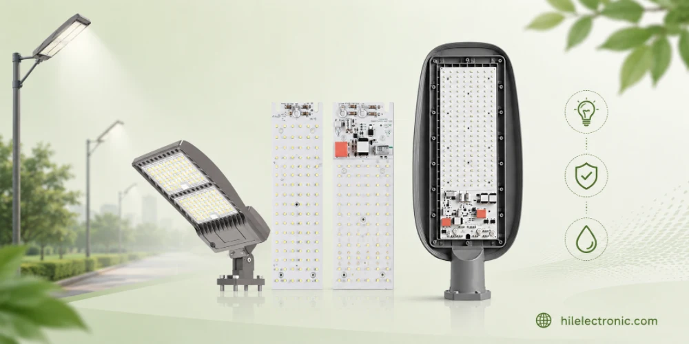
Outdoor Lighting PCB Manufacturing & Assembly by Highleap Electronics
Figure 1. outdoor lighting PCB production and assembly...

Lighting PCB Manufacturer: PCB Fabrication, PCB Assembly & Turnkey LED Lighting
Figure 1. Lighting PCB manufacturer overview for LED light...
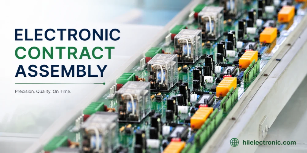
Electronic Contract Assembly: Models, Selection, and the Full Build Process
Figure 1. Electronic Contract Assembly reference image for...
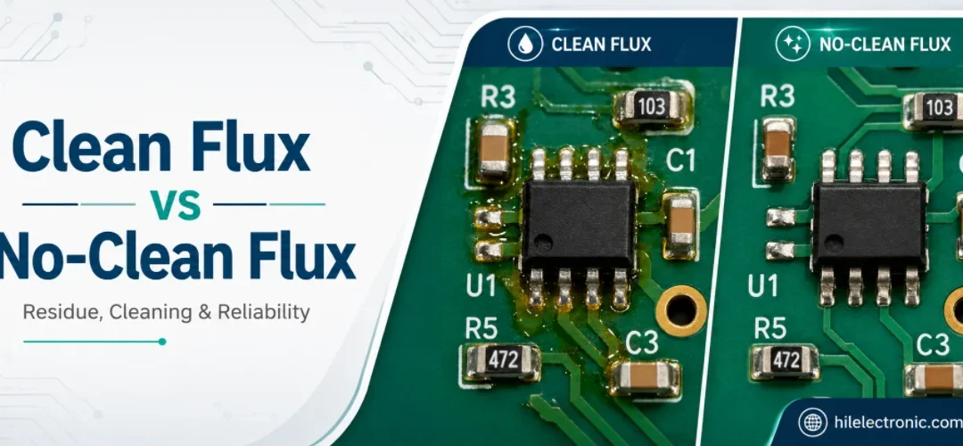
How to Clean Flux Off a PCB: The Right Method for Each Flux Type
Figure 1. How To Clean Flux Off Pcb reference image for...
How to get a quote for PCBs
Let’s run DFM/DFA analysis for you and get back to you with a report. You can upload your files securely through our website. We require the following information in order to give you a quote:
-
- Gerber, ODB++, or .pcb, spec.
- BOM list if you require assembly
- Quantity
- Turn time
For PCBA services, please provide your BOM (Bill of Materials) and any specific assembly instructions. We also offer DFM/DFA analysis to optimize your designs for manufacturability and assembly, ensuring a smooth production process.