
Back to blog
20 Analog Circuits Engineers Should Master

In the realm of electronics, understanding analog circuits is akin to mastering the language of technology. From converting alternating current to direct current to amplifying signals and filtering noise, analog circuits are the backbone of countless electronic devices. This comprehensive guide explores 20 essential analog circuits, delving into their key points, functions, and calculations. Whether you’re an aspiring engineer or a seasoned professional, this guide serves as a valuable resource for understanding and designing analog circuits.
Bridge Rectifier Circuit

Key Points:
- Unidirectional Conductivity of Diode: A diode conducts when forward biased and blocks current flow when reverse biased.
- Volt-Ampere Characteristics: Diode behavior is often approximated by ideal switching or constant voltage-drop models.
- Current Direction: In a bridge rectifier, diodes conduct in pairs to convert AC to DC.
Power Filter

Key Points:
- Filtering Process Analysis: Capacitors smooth output voltage by storing charge and releasing it during voltage drops.
- Waveform Formation: Capacitors charge and discharge to maintain stable output voltage.
- Calculation: Capacitor values are chosen based on the desired ripple voltage and load current.
Signal Filter

Key Points:
- Function: Signal filters attenuate unwanted signal components while allowing desired signals to pass.
- Impedance Calculation: LC circuits’ impedance depends on the frequency and component values.
- Passband Curve: Filters exhibit different frequency responses based on their design.
Differential Circuit and Integral Circuit

Key Points:
- Function: Differential circuits amplify the difference between two input voltages, while integral circuits perform mathematical integration.
- Analysis: These circuits’ voltage waveforms are determined by their component values and input signals.
- Calculation: Time constants and component values are critical for circuit design and performance.
Common Emitter Amplifier Circuit

Key Points:
- Structure: This circuit uses a transistor in a common emitter configuration to amplify signals.
- Amplification Factors: Gain and phase relationships are crucial for understanding the circuit’s behavior.
- Calculation: The transistor’s characteristics and biasing determine the amplifier’s performance.
Common Collector Amplifier Circuit (Emitter Follower)

Key Points:
- Role of Components: This circuit provides high input impedance and low output impedance.
- Feedback Analysis: Negative feedback improves stability and reduces distortion.
- Calculation: Biasing and load resistance affect the circuit’s performance.
Circuit Feedback Block Diagram

Key Points:
- Feedback Types: Understanding positive and negative feedback helps in analyzing circuit behavior.
- Amplification Gain: Negative feedback reduces gain but improves stability and reduces distortion.
- Impact of Feedback: Feedback affects the circuit’s input and output characteristics.
Zener Diode Circuit (Simple)

Key Points:
- Characteristics: Zener diodes operate in the breakdown region to regulate voltage.
- Application Considerations: Proper circuit design is crucial for reliable voltage regulation.
- Voltage Stabilization: Zener diodes maintain a constant voltage across the load.
Series Regulated Power Supply

Key Points:
- Design Overview: Series regulators provide stable output voltage despite input variations.
- Function of Components: Transistors and resistors control the output voltage and current.
- Calculation: Component values are chosen to achieve the desired output voltage.
Operational Amplifier Circuit

Key Points:
- Ideal Op-Amp: Operational amplifiers are modeled as ideal devices with specific characteristics.
- Inverting Op-Amp Circuit: These circuits provide voltage gain with a virtual ground at the inverting input.
- Gain Expression: The gain of an inverting op-amp is determined by the feedback resistor ratio.
Differential Op-Amp Circuit

Key Points:
- Characteristics: Differential op-amp circuits amplify the voltage difference between two inputs.
- Operation: The output voltage is proportional to the voltage difference between the inputs.
- Application: These circuits are used in instrumentation and signal processing.
Voltage Comparator Circuit

Key Points:
- Function: Voltage comparators compare two input voltages and produce a digital output.
- Characteristics: The comparator’s output switches based on the input voltage levels.
- Hysteresis: Adding hysteresis prevents output oscillation near the switching threshold.
RC Oscillator Circuit

Key Points:
- Oscillation Conditions: RC oscillators rely on the phase shift in the feedback network for oscillation.
- Frequency Determination: The oscillation frequency depends on the RC time constants.
- Waveform Analysis: Voltage waveforms across components oscillate with a specific frequency and phase relationship.
LC Oscillator Circuit

Key Points:
- Analysis: LC oscillators use inductors and capacitors to create resonant circuits.
- Frequency Determination: The oscillation frequency is determined by the LC tank circuit’s resonant frequency.
- Operation: LC oscillators generate sinusoidal signals with minimal distortion.
Quartz Crystal Oscillator Circuit (Series)

Key Points:
- Crystal Characteristics: Quartz crystals exhibit precise frequency stability and low phase noise.
- Oscillator Operation: The crystal’s resonance determines the oscillator’s frequency.
- Applications: Quartz crystal oscillators are widely used in clocks, communication systems, and instrumentation.
Power Amplifier Circuit

Key Points:
- Class B Amplifier Operation: Class B amplifiers provide high efficiency but suffer from crossover distortion.
- Composite Transistors: Combining transistors can improve performance and power handling.
- Class A vs. Class B: Class A amplifiers offer low distortion but lower efficiency compared to Class B amplifiers.
For production planning, it also helps to compare this topic with PCB design review and PCB fabrication capability before finalizing the fabrication or assembly package.
Here are some additional circuit diagrams. For further information, please contact us at Highleap Electronic. We welcome discussions and consultations on any electronic issues:


Conclusion
As technology continues to advance, the importance of analog circuits remains steadfast. Their role in converting, filtering, and amplifying signals is fundamental to the functionality of electronic devices. By mastering the principles outlined in this guide, you can unlock endless possibilities in the world of electronics. For further insights into analog circuit design and applications, stay tuned to Highleap Electronics. And remember, for any electronic issues or consultations, don’t hesitate to contact us at Highleap Electronic.
At Highleap Electronic, we understand that the backbone of your electronic devices lies in the quality and reliability of your PCBs and PCB assemblies (PCBA). As you delve into the intricacies of analog circuit design, such as those described in our comprehensive guide, we invite you to partner with us for all your PCB and PCBA needs.

Related Articles
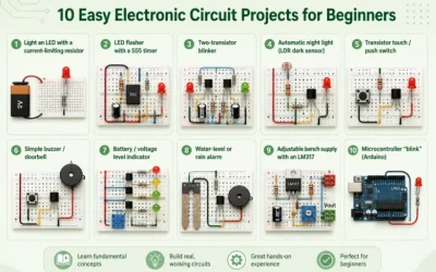
Electronic Circuit Projects for Beginners
Last updated: May 2026 · A hands-on starter guide for students, hobbyists, and self-taught makers The best beginner electronics projects are simple, cheap,

PCA vs PCB vs PCBA: What Is the Difference?
Learn the difference between PCA, PCB, and PCBA with simple definitions, examples, and the terms buyers and engineers actually use.

Protoboard vs Breadboard: Which to Use
Last updated: May 2026 · A plain-English guide for students, hobbyists, and engineers building their first circuits The difference between a protoboard and