
Back to blog
Ensuring Excellence in Camera FPC Manufacturing: Quality Issues and Control Points

Since the camera FPC generally has dense pads and needs to be reinforced with steel sheets, there will be various quality abnormalities. So how to control these quality abnormalities?
1. Abnormal quality when laminating the covering film
1. The solder pad is covered (the covering film is attached to the upper pad or the glue overflows a lot), resulting in poor welding effect;
2. Fitting leaky lines: Because the pads are dense and the circuits are complex, it is difficult to have room to expand the pads in the design, resulting in the minimum gap between the pads (the outer edge of the covering film) and the circuits being as low as 0.075mm. , this size is very challenging for the naked eye to fit the cover film, so leakage often occurs, which makes it easy for customers to have micro short circuits during the SMT and CMOS processes, that is, the solder points are connected to the circuit, but it is difficult to detect. , the undesirable phenomena that customers experience after installation include disconnection, bright spots, shadows, interference, dead spots, oil stains, light leaks, horizontal and vertical lines, ripples, red and green, no response, no picture, etc. They are very complicated and are actually caused by Caused by micro-short circuits in the SMT solder caused by leaky bonding wires.
Improvement measures: Since the accuracy of printing solder mask ink is high, and the solder mask oil can replace the electrical and mechanical properties of the pad area covering film, this process can be used to replace it. Sun Company PSR9000 ink is usually used. If the customer does not allow it, When using solder resist oil, you can use a special cover film for camera FPC (the amount of glue overflow is small), and use TPX instead of the general release film during lamination to limit the amount of glue overflow from the cover film as much as possible.
Abnormal quality during steel plate reinforcement assembly
The camera FPC will be mounted with a CMOS component, which is very fragile. For this reason, steel sheets are usually chosen to reinforce the back of the FPC to support and protect the components. The following problems are often encountered in the process of laminating steel sheets for reinforcement:
1. Insufficient peel strength of the steel sheet reinforcement: Grease will be used during the processing of the steel sheet. If the oil is not removed (residual), the adhesion will be affected after the glue is applied, resulting in insufficient peel strength;
Improvement strategy: Before pasting glue on the steel sheet, use NaOH solution to clean it (to facilitate batch operations, the stripping section at the rear of the DES line can be used to complete it), and then wash and dry with pure water. At the same time, the FPC board surface must be thoroughly cleaned with alcohol. After the steel sheet reinforcement is assembled and pressed, it must be baked at 150°C for 1 hour so that the glue can be completely solidified. When baking, be careful not to stack products to avoid uneven temperatures. , it is best to use a layer rack to ensure uniform baking temperature.
2. Deviation of steel sheet reinforcement: Manual alignment of the steel sheet will have an impact on the customer’s assembly. In particular, the reinforcement of the steel sheet with mounting holes will cause the cover mounting holes to affect the customer’s assembly;
Improvement strategy: Use a jig to position and assemble steel sheets for reinforcement. The jig can be made of acrylic or steel, with several positioning pins set diagonally.
3. Glue overflows when the steel sheet is reinforced and pressed: The steel sheet glue will flow under high temperature and high pressure conditions during lamination, causing glue to overflow. In severe cases, it may cause the steel sheet to reinforce the positioning holes and affect the customer’s assembly;
Improvement strategies: The aperture of the steel sheet should be slightly larger than the FPC aperture during design, leaving space for the glue to flow so that it will no longer block the hole. The size depends on the distance between the edge of the hole and the product appearance. Generally, it is better to be greater than 0.1-0.15mm. .
For related manufacturing decisions, Highleap also documents production PCB manufacturing and PCB electrical testing, which can help prevent unclear notes in the quote package.

Related Articles

Exploring Through-Hole Technology (THT) in PCB Assembly
The article details the THT PCB Vertical Plugin automation and the benefits and applications of THT.
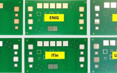
PCB Surface Finish Guide for 7 Common Options
A practical PCB surface finish guide covering HASL, lead-free HASL, ENIG, OSP, immersion silver, immersion tin, hard gold, and ENEPIG selection.
What is a Cold Joint Solder and How Can You Prevent it?
By adhering to these guidelines, you can minimize the risk of cold solder joints and ensure the integrity of your PCB assemblies.