
Cable TV Box PCB Design and Manufacturing

A cable TV box PCB is built around digital cable reception, with an RF input, tuner and demodulation chain connected to digital processing and user-facing interfaces. Depending on the product and cable network, the board may also include conditional-access functions, HDMI, USB, Ethernet, storage and software-update capability. Highleap Electronics manufactures the PCB and PCBA side of these customer-defined designs without assuming that every cable receiver uses the same standard or service architecture.
- Cable TV Box PCB Manufacturing for OEM and ODM Projects
- Cable RF Front End, Tuner and Demodulation Architecture
- Conditional Access, Firmware and Operator-Specific Configurations
- HDMI, USB, Ethernet and Cable Box PCBA Assembly
- Cable TV Box Functional Testing and Failure Diagnosis
- Related Cable Receiver Boards and Regional Sourcing
- PCB Manufacturing Files, Box Build Scope and Production Control
Cable TV Box PCB Manufacturing for OEM and ODM Projects
The cable input, tuner and demodulator are central to the board. DVB-C and DVB-C2 are digital cable standards, while actual operator deployments and product implementations can differ. DVB-C2 is defined for digital television broadcasting over HFC cable networks and related installations. The manufacturing package should identify the actual standard and tuner/demodulator configuration required by the product.
See the DVB material for DVB-C2 when the project uses that standard.
Cable, Satellite, Terrestrial and Android TV Boxes Are Not Interchangeable
The products may all contain HDMI and a processor, but their receiving hardware is different. A cable box starts with a cable RF input and cable demodulation chain; a satellite receiver uses a satellite/LNB environment; a terrestrial receiver uses an antenna input and terrestrial standard; an Android TV box is a general embedded smart-TV platform and does not inherently provide broadcast reception.
| Product type | Primary input architecture | Manufacturing emphasis |
|---|---|---|
| Cable TV box | Cable RF input and cable tuner/demodulator | RF path, tuner, demodulation, access/service configuration. |
| Satellite receiver | Satellite RF/LNB path | RF front end, tuner and satellite demodulation. |
| Digital terrestrial receiver | Terrestrial antenna input | Market-specific terrestrial tuner/demodulator. |
| Android TV box | Network/local media interfaces | SoC, memory, storage, HDMI and wireless; broadcast reception is product-dependent. |
Cable RF Front End, Tuner and Demodulation Architecture
The RF input connector, tuner and nearby shielding form a sensitive part of the board. Manufacturing should preserve the intended routing and component placement. The coaxial connector also experiences mechanical loading during cable insertion, so solder and mechanical support need inspection appropriate to the connector design.
Highleap supports RF PCB manufacturing and RF shielding where these controls are part of the customer’s design.
Tuner, Demodulator and Transport Processing
After the RF front end, the receiver recovers a digital stream and the board may process, decode and route that data to HDMI or other outputs. The actual decoder and service architecture are product-dependent. It is better for the manufacturing article to define the signal path at this level than to assume a particular chipset or codec for every cable box.
- Cable inputRF connector and front-end integrity.
- TunerChannel selection and RF-to-baseband conversion defined by the design.
- DemodulatorRecovery of the transmitted digital data using the specified cable standard.
- Digital processorTransport handling, decoding, user interface and service functions as required.
- OutputHDMI, AV, USB or other interfaces included in the product.
- Network/serviceEthernet or other network features only when part of the released SKU.
DVB-C and DVB-C2 Should Be Treated as Design Inputs
DVB-C2 is a second-generation digital cable transmission system for cable networks and related installations. A cable TV box may use DVB-C, DVB-C2 or another cable architecture depending on the target network. The product page should therefore avoid implying that every cable box uses the same tuner, modulation handling or demodulator chipset.
The DVB-C2 specification describes the transmission system while leaving receiver-side implementation choices open. In practice, the PCB manufacturer needs the customer’s actual tuner/demodulator configuration and test environment rather than a generic statement about cable TV.
Cable Input Testing Should Be Repeatable
The RF source should be defined in the test instruction. A signal generator, approved cable-network simulator or reference source can provide repeatability; an uncontrolled live network may not. The production test should record whether the board acquired the intended channel/service and whether output was correct.
Conditional Access, Firmware and Operator-Specific Configurations
Some cable service environments use conditional-access technology, but not every cable box uses the same mechanism or physical interface. The PCB may contain a security device, card interface or secure processing block depending on the operator and product. The correct manufacturing test is therefore the customer’s specified authorization or interface check, not a generic statement that all cable boxes contain a particular security module.
Firmware and Hardware Revision Must Stay Linked
Cable boxes often have hardware and software versions that evolve together. A new tuner or memory option can require corresponding firmware changes. Production records should therefore identify PCB revision, BOM revision, programmed image and test revision together.
Operator Variants Need a Controlled Hardware Matrix
A common cable-box PCB can support different operators or markets through software, conditional-access configuration, tuner options or populated components. A production matrix can make those differences explicit and keep the factory from building a hybrid configuration that was never validated.
| Variant | Possible difference | Production control |
|---|---|---|
| Operator software | Service/UI configuration | Firmware version and configuration file. |
| Tuner option | Supported RF range or architecture | Approved BOM and first-article validation. |
| Security/access | Operator-specific conditional access | Controlled component and authorization test. |
| Network | Ethernet or other connectivity | SKU-specific functional test. |
| Storage | Different capacity or package | BOM and programming mapping. |
Cable Operator Requirements Can Change the PCBA Test Flow
A cable receiver that is intended for a specific operator environment may require a different software image, authorization flow or regional configuration from another customer using similar hardware. Those differences should be captured in the production release rather than embedded in informal operator knowledge. The test fixture can then select the correct sequence based on the production SKU.
HIGHLEAP ELECTRONICS • PCB MANUFACTURING & PCBA
Send your PCB files, BOM, RF requirements, assembly data and expected quantity. Highleap supports customer-designed cable TV box boards through PCB fabrication and PCBA, including prototypes, repeat orders and large-volume production with competitive pricing and extended after-sales support.
HDMI, USB, Ethernet and Cable Box PCBA Assembly
External interfaces create both electrical and mechanical requirements. HDMI and USB need correct high-speed routing and connector placement; Ethernet requires the approved PHY and magnetics arrangement where network access is included. USB connectors also experience repetitive insertion force, so solder and anchoring should be inspected.
Highleap has resources for communication interfaces, USB hub PCB and PCB assembly when these functions are part of the customer design.
Assembly Inspection for Cable Receiver Boards
Cable box PCBs can combine RF parts, fine-pitch processors, memory, connectors and BGA packages. AOI can cover many SMT joints while X-ray can be considered for hidden solder joints. RF connector soldering deserves its own visual and mechanical inspection because an intermittent cable input can present as a tuner problem.
Final Assembly Can Change Connector Stress
Cable boxes often place RF, HDMI, USB and power connectors around the enclosure perimeter. Once cables are attached, board flex and connector loading can differ from the bench setup. First-article inspection should therefore include the final mechanical interface where cable force could affect the assembly.
Cable TV Box Functional Testing and Failure Diagnosis
A useful fixture starts with a defined RF test condition and continues through channel acquisition and the user-facing outputs. The exact test source, frequency/channel, expected lock condition and output content should be supplied by the product owner.
- Power-up: verify startup and current behavior under the approved condition.
- Firmware: verify the expected software revision and hardware configuration.
- RF source: connect the approved cable test source.
- Acquisition: verify tuner and demodulator behavior.
- Output: confirm HDMI/AV or other required output.
- User control: exercise remote/front-panel functions included in the SKU.
- Service functions: verify Ethernet, USB, storage or updates only when specified.
- Access control: run the customer’s approved conditional-access or security test when applicable.
Highleap can implement functional testing and integrate customer-provided fixtures where appropriate.
Common Cable Box Failure Categories
A useful production record can classify failures by front-end, processing, output, control or provisioning stage. This helps engineering identify whether corrective action belongs to PCB assembly, component sourcing, firmware or system integration.
- Front-end failure: RF connector, tuner, demodulator or associated power/control path.
- Digital processing failure: processor, memory, storage or firmware.
- Output failure: HDMI/AV connector, routing, software configuration or display interface.
- Control failure: IR receiver, buttons or front-panel connector.
- Provisioning failure: wrong firmware, configuration or operator-specific security setup.
RF and Digital Failures Should Be Diagnosed Separately
A cable box can show no picture because the RF front end did not acquire a signal, because the decoder failed, because firmware is wrong, or because the HDMI output is defective. A staged test prevents all of these faults from being reported as the same problem and helps the factory identify whether a corrective action belongs to assembly, component sourcing, firmware or system integration.
| Failure stage | Useful evidence |
|---|---|
| RF front end | Input source present, tuner initialized, acquisition result. |
| Demodulation | Lock status or approved signal result. |
| Processing | Firmware/version and known-good stream behavior. |
| Output | Reference display result and connector inspection. |
| Provisioning | SKU, software image and operator configuration. |
Related Cable Receiver Boards and Regional Sourcing
A cable TV box may be surrounded by a tuner module, RF front-end section, conditional-access interface, multimedia decoder, storage, network interface and power circuitry. In some designs these functions are consolidated into one mainboard; in others they are divided across modules or boards.
Related product terms include cable receiver PCB, DVB-C receiver board, QAM receiver PCB, cable set-top box mainboard, RF tuner board and conditional-access interface board. These are useful for describing neighboring hardware needs, but they should not be treated as interchangeable products.
Highleap Electronics manufactures and assembles the customer-released PCB/PCBA. It does not operate a cable television service and does not sell the finished cable box as a consumer brand.
Regional Cable-TV Hardware Sourcing
Cable television hardware is highly market-dependent because operators, network architectures and conditional-access arrangements vary. A US or Canadian OEM should identify the target cable system and approved tuner/demodulator architecture. European teams in Germany, France, Italy and the UK may use different operator or service configurations. The region therefore belongs in the product specification when it changes the electronics, not as a block of city names added for search visibility.
Useful adjacent terms include cable set-top box PCB manufacturer, DVB-C PCB assembly, QAM tuner board, cable receiver mainboard and RF set-top box PCBA. These terms naturally support procurement-oriented content when the corresponding circuitry is actually discussed.
PCB Manufacturing Files, Box Build Scope and Production Control
A strong manufacturing package includes Gerber or ODB++ data, fabrication drawing, stackup or impedance notes where required, BOM, pick-and-place, assembly drawing, RF component requirements, firmware, connector details and test instructions. If the cable box has different operator or regional SKUs, provide a variant matrix identifying the hardware and software differences.
When Box-Build Scope Is Needed
If Highleap is asked to assemble the PCB only, the manufacturing scope ends at the PCBA. If the project also requires enclosure assembly, cables, displays, buttons, shielding or other finished-product work, those operations should be specified separately. Highleap offers turnkey box-build assembly for projects that extend beyond the PCB.
A Repeatable Cable Receiver Requires Controlled Inputs and Testing
The production goal is consistency: the correct RF front end, the approved digital processing hardware, the correct software configuration and a functional test that matches the customer’s service environment. Highleap Electronics can support PCB fabrication, assembly and testing while leaving broadcast-standard and operator-specific decisions under the customer’s released product specification.

Recommended Posts
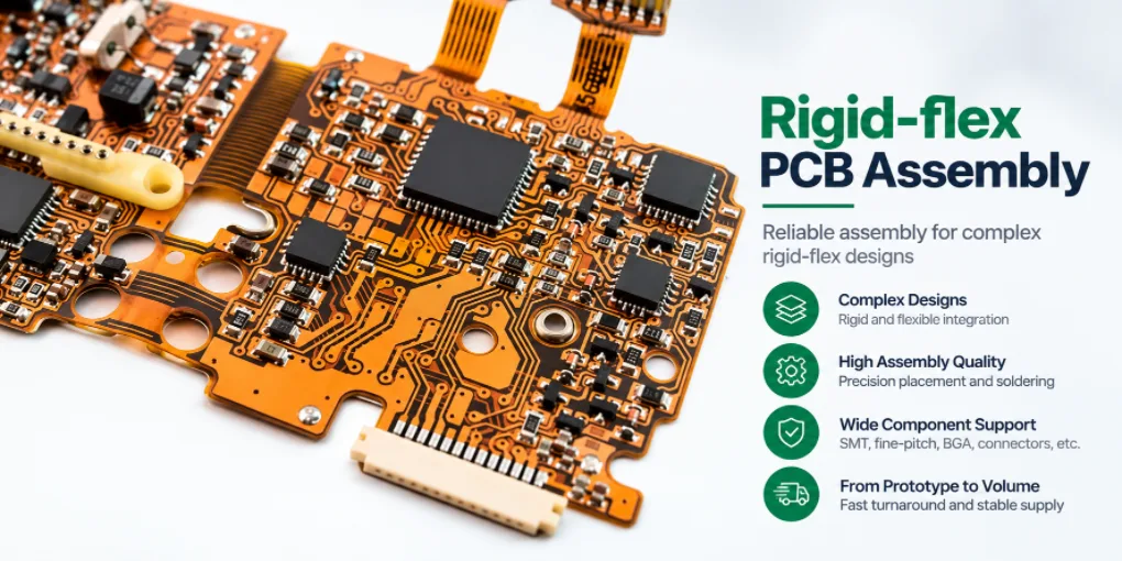
Rigid-flex PCB Assembly for Prototype and Production
Figure 1. Rigid-flex PCB assemblyRigid-flex PCB assembly...

1206 PCB Assembly Services for Prototypes & Production
src="https://hilelectronic.com/wp-content/uploads/2026/08/PC...

Kitted PCBA Services for Customer-Supplied Components
Kitted PCBA is a manufacturing model in which the customer...

Build to Print PCB Assembly Services
src="https://hilelectronic.com/wp-content/uploads/2026/08/PC...
How to get a quote for PCBs
Let’s run DFM/DFA analysis for you and get back to you with a report. You can upload your files securely through our website. We require the following information in order to give you a quote:
-
- Gerber, ODB++, or .pcb, spec.
- BOM list if you require assembly
- Quantity
- Turn time
For PCBA services, please provide your BOM (Bill of Materials) and any specific assembly instructions. We also offer DFM/DFA analysis to optimize your designs for manufacturability and assembly, ensuring a smooth production process.